


The Iron Man Arc Reactor Clock is a creative clock inspired by the famous arc reactor from the Iron Man movie. Not only does it have the time display function of a traditional clock, it also incorporates cool blue LED lighting to mimic the visual effect of the arc reactor. Whether placed on a desk, bookshelf or nightstand, the Arc Reactor Clock adds a sense of technology and futuristic feel to the environment. Let's see how to make it next!
Accessories needed
-
Copper wire 0.5 mm (19 meters)
-
Copper wire 0.8 mm (60 cm)
-
Clear enameled copper wire 0.3 mm (50 cm)
-
Black PLA
-
Clear PLA
-
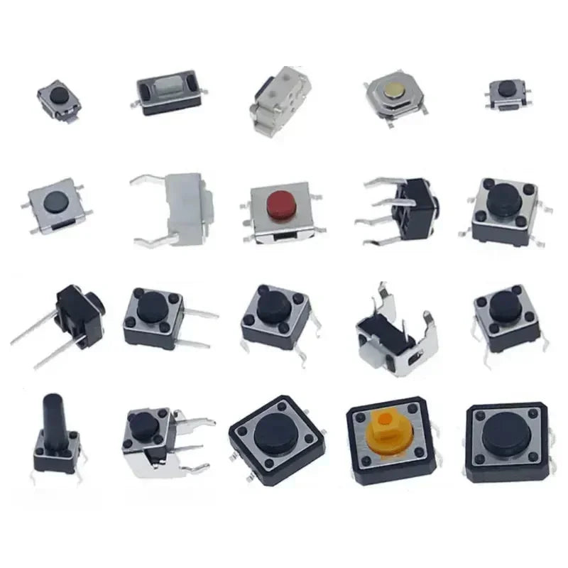
1x - Touch Sensor (TPP223)
-
3x - M3 x 8mm screws
-
4x - M2 x 6mm screws
-
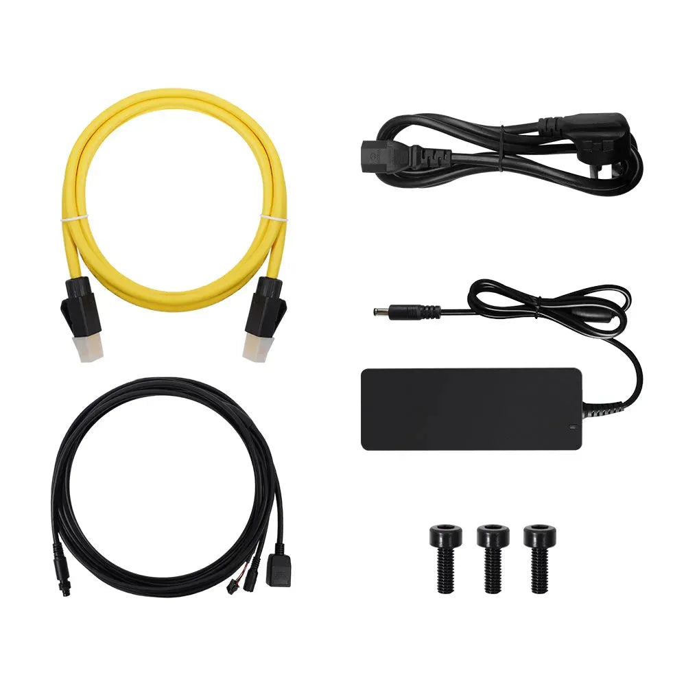
Cord
-
If Basic Diode/LED Center
Step 1: Printing
Print all parts using the following settings. The STL file name begins with the PLA color to be used.
Layer: 0.2mm
Fill: 20%
For detailed printing information, see: Iron Man Arc Reactor Clock Printing Information
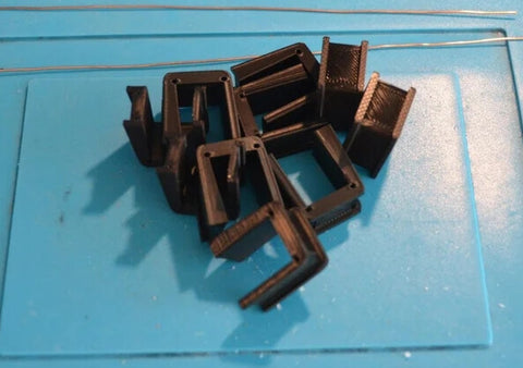
Part "Black - Copper-coil-support" has to be printed 10 times
Step 2: Transparent Ring and Coil Holder
Here you need some 0.8 mm copper wire:
-
1x 33 cm
-
1x 24 cm
-
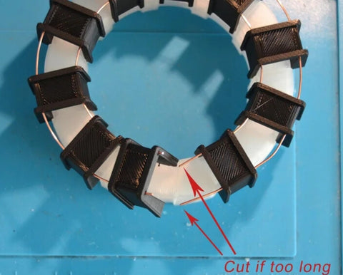
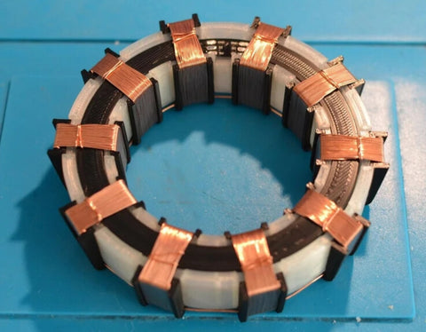
Take the 10 copper coil supports and align them (the thickest leg is near you, see picture)
-
33 cm copper wire will pass through the hole of the thickest leg
-
24 cm copper wire will pass through the hole of the thinnest leg
-
align all coil supports (thickest leg on the outside) with the clear ring (cut off excess copper wire if needed)
-
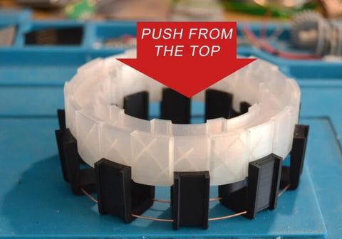
Push from the top
-
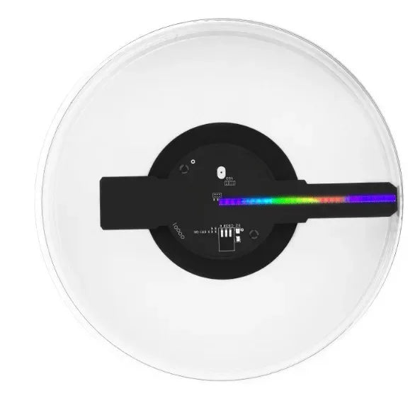
Use a file to remove any “dirt” from the LED ring PCB, if needed.
-
Remove the LED ring (remove existing wires if necessary) and place it inside the clear ring with the LED facing down. Check that the pads are close to the opening of the clear ring (see figure).
-
Add LED ring spacer to the top of the LED ring
Step 3: Copper Coil Wiring

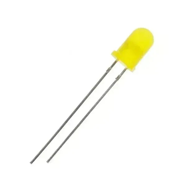
Step 4: Option a - Blue Diode/LED Center
For this step you will need:
-
2x - Blue Diode
-
2x - 47 Ohm Resistor
-
ESP32
-
Small heat shrink tubing
-
on each diode, solder a 47 ohm resistor to the negative pin (the shorter one)
-
Use heat shrink to protect the solder
-
Solder two diodes to the ESP32, one on each side, as shown.
Step 5: WS2812B RGB LED Center
For this you need:
-
0.3mm enameled copper wire.
-
2x-WS2812B LED
-
ESP32
-
Cut/bend the wires to enable soldering as shown.
-
Use double sided desktop office tape to hold the WS2812B LED in place while soldering. Note the orientation of the LEDs and check the pinouts shown in the picture for assistance.
-
Remove the protective layer of copper to be soldered (scrape it off with a knife)
-
Solder copper wires to the LEDs
-
Cut 2 pieces of thick double sided tape measuring 5mm x 5mm and attach them to the LED holder.
-
Place the LED into the bracket and bend the wires as shown in the figure. 7.
-
There are small slots underneath the bracket where you can place the wires. You can use a soldering iron to melt the bracket a little to block the wires so they don't move.
-
place the LED bracket on the ESP32 and solder the wires as shown (picture and wiring diagram)
Step 6: Soldering Wires on the ESP32
Use this wiring diagram as a guide to put the parts together
Step 7: Solder the Touch Sensor
For this you will need:
-
12 cm green wire (you can see it in the first picture, I used white wire for assembly, but I got confused because the LED ring signal wire is also white, so I switched to green)
-
Touch sensor
Notes:
-
The touch sensor will be used “remotely”, to do this we have to solder a wire to it and this wire will also be soldered to one of the copper coils you made at the beginning.
-
The touch sensor can be very sensitive and sometimes the font switching is triggered even if you don't activate the touch sensor. To avoid this, you can solder a 50 uF capacitor between the pad where the white wire will be soldered and the other pad closest to the first pad. This should reduce the sensitivity of the touch sensor.
Step 8: Putting the ESP32 into the Master
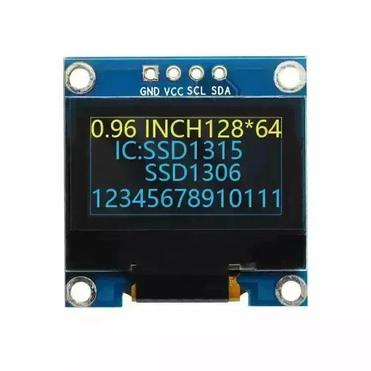
Step 9: Connecting the OLED screen
For this step, you need to:
-
OLED screen
-
Top OLED screen housing
-
Bottom OLED screen housing
-
4 M2 screws
-
Small heat shrink tubing
-
First carefully remove any potential “dirt” from around the OLED screen PCB. If not, it may not fit in the housing. 2.
-
Carefully bend all 4 pins of the OLED screen a little bit (about 30 degrees). We have to do this so that they don't touch the parts behind them (see picture).
-
Use cutting pliers to shorten the pins on the top of the OLED screen (again so that they fit inside the housing).
-
use a M2 screw to “prepare” the hole at the bottom of the housing. 5.
-
Alternatively, use a 2mm drill bit to “prep” the hole at the top of the enclosure. 6.
-
Place the OLED screen into the enclosure and secure all parts in place using four M2 screws. 7.
-
Cut 4x 5mm heat shrink tubing.
-
Solder the OLED wires to the appropriate pins (see picture)
Step 10: Install the OLED screen
For this step you will need:
-
Transparent ring support 3D piece
-
Multi-ring 3D piece
-
Porous Ring 3D Piece
-
3 M3 screws
-
Place the clear ring support on the base. Take care to properly align the arrows on the pieces so that they are above the holes through which the LED loop wires pass.
-
Remove the multi-ring and place it on the clear ring holder. You can align it with the bracket as desired.
-
Add the poly ring so that the OLED screen housing passes through it. Be careful to properly align the holes in the porous ring with the holes in the OLED screen housing (there are three “larger” 3mm holes in the porous ring).
-
Secure all parts in place with 3 M3 screws.
Step 11: Final Assembly
Step 12: Code Upload and Configuration
The code can be found on GitHub: https://github.com/LuluTchab/IronManArc
There you will find all the information you need about uploading the code.
Note: Depending on the option you choose for the center (blue diode/LED vs. WS2812B), you must comment/uncomment one line of code before uploading it to the ESP32.
Once the code is uploaded to your Iron Man Arc Reactor, it will display an error, which is normal. Please follow the steps below.
-
keep the Arduino program open and turn on the serial monitor at 115200 bps
-
If the menu is not yet displayed, type only the “?” character and press ENTER
-
now navigate through the menus by typing the menu number (and pressing ENTER) to configure what you want.
The end of the time lapse video shows how to configure everything and how the Iron Man Clock Reactor works.