Skip to content

+49 1626571232

info@openelab.io

🚀 Free Shipping from 50€ in EU / 80€ Worldwide

How to Make Your Own Smart Thermostat

26 Jul 2024 0 Comments
Smart Thermostat is an advanced temperature control device for use in home and commercial environments. Users can adjust the temperature settings anytime, anywhere and manage it remotely through a smartphone app or web interface. The aim of this project is to create an easy-to-use, user-friendly and open-source Smart Thermostat that you can create according to your specific needs.
 

Hardware Components:

  1. Microcontroller: Arduino MKR WiFi 1010 (Microcontroller to process sensor data and control the heating system. It has WiFi and Bluetooth capabilities).
  2. Sensors: Humidity and temperature sensor: BME280 Humidity Pressure Temperature Sensors
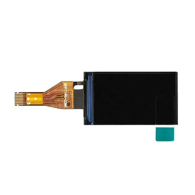
  1. OLED Display: 0.96 inch OLED SSD1306 Display I2C 128 x 64 pixels
  2. Relay Module: 5V/12V Relay Module, used as a switch to control the heating system.
  3. Real Time Clock: Real Time Clock RTC DS3231 I2C real time clock (for tracking accurate time)
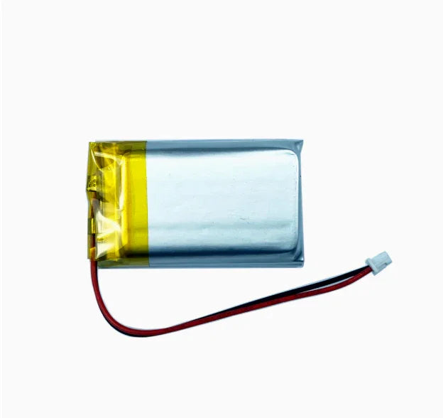
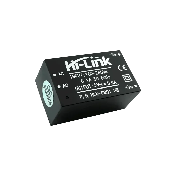
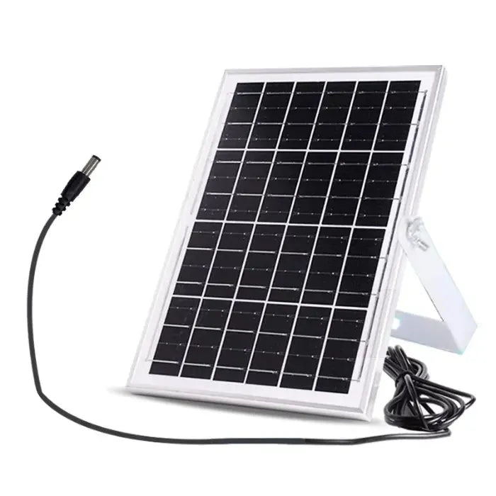
  4. power supply: 5V/2A power adapter
  5. housing: 3D printed (see draft in this note) or retrofit box to accommodate components
  6. circuit board
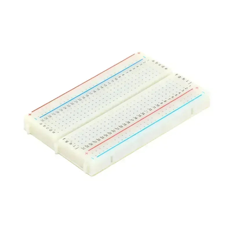
  7. breadboard and jumpers (if you want to run it as a prototype and possibly expand it)
  8. custom printed circuit board (design it using KiCad EDA and print it using Eurocircuits)


Software Requirements:

  1. IDE: Arduino IDE (you can use any IDE you like as long as you are able to upload code to Arduino)
  2. Programming: You only need a basic knowledge of assembly and configuration tuning. If you want to expand the project, some experience with the above technologies may be helpful.
  3. Arduino: C++
  4. Database: SQL (MariaDB)
  5. Front-end: TypeScript (Angular17 front-end)
  6. Backend: TypeScript (Node.js, Express)
In most heating systems, the thermostat controls the heater by closing (shorting) the contacts to complete the circuit and activate the heater. This thermostat works on the same principle, using a relay to close the circuit, and if your current thermostat operates in this manner, you can use this thermostat as well.
 

Step 1: 3D Printed Housing  

We designed a simple enclosure to make the thermostat look more sophisticated and more like a typical thermostat. You can download our STL file and import it into Tinkercad or any other 3D modelling software. You can tweak it to your liking and then 3D print it. Our design is very basic and can be used as a prototype so you can improve and customise it as needed.
 
If you want to use the PCB (we designed) to fit exactly in the case you can export the PCB layout from KiCad as a SVG file and import it into your 3D modelling software. This way you can design the case around the PCB and make sure everything fits. Thermostat_Case.stl
 

Step 2: Print the PCB


Step 3: Assemble Hardware and Microcontroller Setup


Microcontroller Setup

Start the assembly process by setting up the microcontroller. Mount it on a breadboard so that it can be prototyped and connected more easily. Connect the microcontroller to a power source, making sure it receives a stable 5V/2A supply. This initial setup forms the basis of the thermostat, providing the necessary control and processing power for the remaining components.

Sensor Integration

Next, integrate the temperature and humidity sensors with the microcontroller. Depending on the type of sensor you choose, follow the specific wiring diagram to connect them properly. For the Adafruit sensor listed above, you can find it on their website. The sensor will provide real-time data about the ambient temperature and humidity, which the microcontroller will use to adjust the heating system. Secure the sensor in a position where it can accurately measure the room temperature.

OLED Display Connection

Connect the OLED display to the microcontroller, ensuring that the pins are configured correctly. The display will be used as a user interface to show the current temperature, set temperature and other relevant information. Proper connection of the display is critical for clear and accurate display output.

Relay Module Setup

Set up the relay module that will control the heating system based on temperature readings and user inputs. Connect the relay to the microcontroller to ensure it can handle the load of the heating system. The relay acts as a switch and the microcontroller can turn it on or off to regulate the temperature. Test the relay operation to ensure that it responds correctly to control signals from the microcontroller.

Step 4: Programming the Thermostat

 
The main loop function runs continuously and performs the following tasks:
  1. periodically sends a heartbeat to the server.
  2. if the heartbeat is successful, queues the sensor data request.
  3. processes all pending requests in the queue.
  4. attempts to reconnect if in fallback mode and sufficient time has elapsed.
  5. controls the heating relay based on temperature while in fallback mode.
  6. update the display periodically.
 
Setting up the development environment
Set up the development environment on your computer by installing the necessary software. If you are using Arduino, download and install the Arduino IDE. for Raspberry Pi, set up the appropriate development environment. Make sure you have all the libraries you need for the temperature sensor, LCD display, and any other components you are using. This setup will provide the tools you need to write, upload, and debug your thermostat code.
 
Uploading Code to the Arduino MKR WiFi 1010
Connecting the Arduino MKR 1010 WiFi
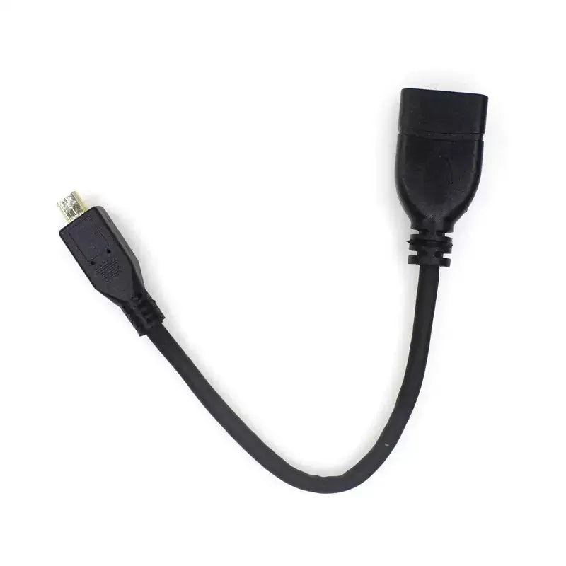
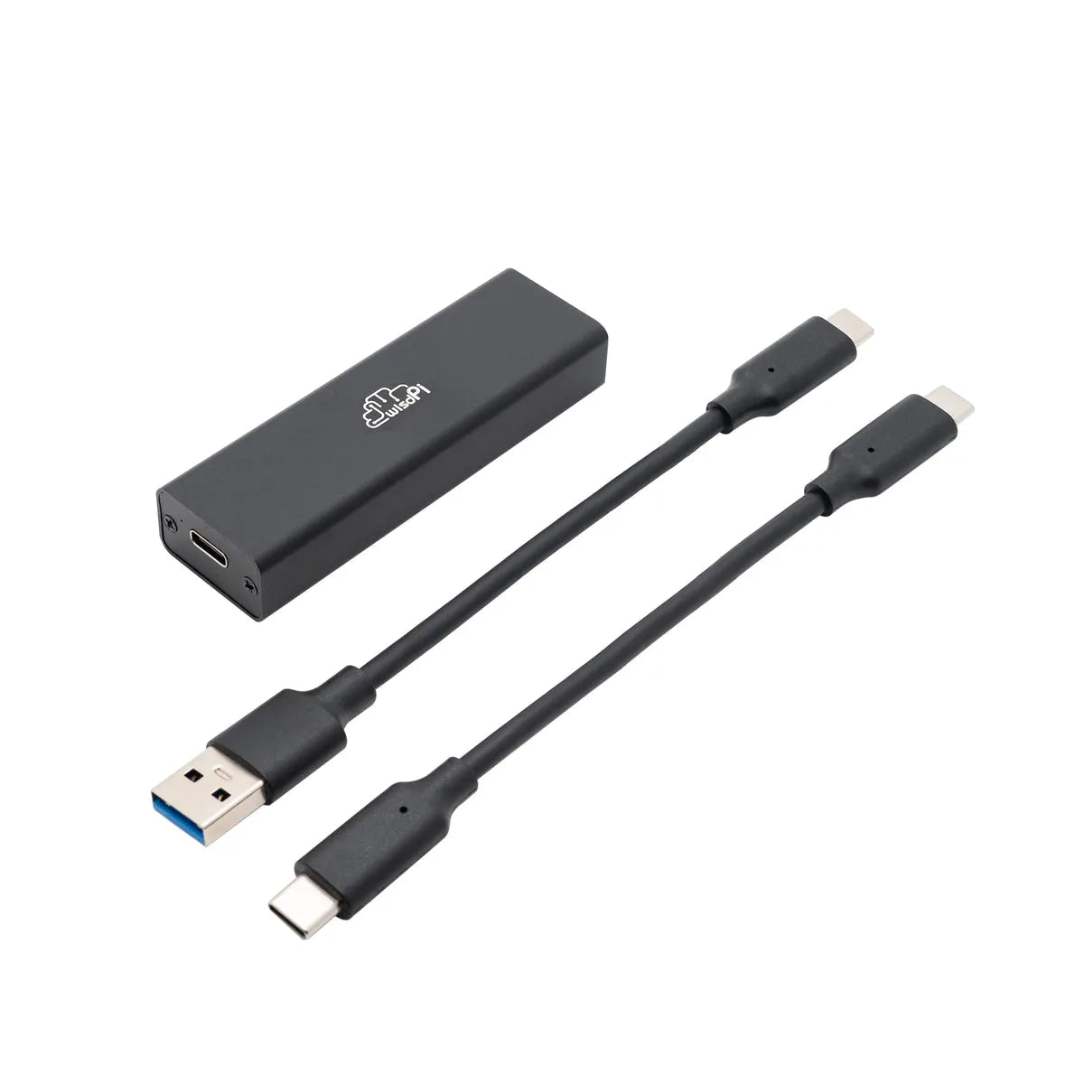
  1. Connect the board: Plug the Arduino MKR 1010 WiFi into your computer using the USB cable.
  2. Select Motherboard: Go to Tools->Motherboard and select Arduino MKR WiFi 1010.
  3. Select Port: Go to Tools->Ports and select the port that corresponds to the board you are connecting to (e.g., COM3, /dev/ttyUSB0).
 
Preparing a Sketch
  1. Open Sketch: Open the Arduino sketch file (.ino) in the Arduino IDE.
  2. Configure Sketch: Modify the sketch to match your server IP, WiFi credentials, and other settings.
 
To upload a sketch
  1. Verify the Sketch: Click the check mark icon in the upper left corner of the Arduino IDE to compile and verify the code. This ensures that there are no syntax errors.
  2. Upload Sketch: Click the right arrow icon next to the check mark to upload the code to the Arduino MKR 1010 WiFi. the IDE will compile the code again and then upload it to the motherboard.
 
Monitoring the Serial Output
  1. Turn on Serial Monitor: Go to Tools->Serial Monitor to turn on the serial monitor.
  2. Set Baud Rate: Make sure the baud rate at the bottom of the serial monitor is set to 9600 to match the Serial.begin(9600); setting in the code.
  3. View Output: You should see output from the Arduino, which includes debug messages and sensor readings.
 
Adjusting the Configuration
You will need to adjust the WiFi and server configurations to match your settings. These configurations must be adjusted to match the server's IP address and WiFi network.
 
Optional: Adjustment of operating variables
These variables and constants manage the operational state, such as connection status, heating status, and timing intervals for the tasks. The FALLBACK_TEMPERATURE is used when the server is unreachable, and the thermostat operates in fallback mode. The HEARTBEAT_INTERVAL determines how often the Arduino sends heartbeats to the server.
 

Step 5: Setting up the Database, Server and Front-end

 
Database
In order for the Smart Thermostat server to function properly, it needs a database. For this, we use MariaDB.
Find information on how to set this up here: GitHub Repositories - Database Setup
 
Frontend
The frontend was developed using Angular17 and allows the user to view data and configure temperature settings.
Find information on how to set this up here: GitHub Repository - Frontend Settings
 
Backend
Developed using Node.js and Express, the backend provides APIs for sensor data, authentication, and heating control.
Find information on how to set this up here: GitHub Repository - Backend Setup
 

Step 6: Testing and Calibration

Initial Test
Switch on the thermostat and perform an initial test to ensure that all components are working properly. Check that the OLED display output is correct and verify that the temperature sensor is providing accurate readings. Test the relay module by setting various temperature thresholds and observing if the relay activates or deactivates the heating system accordingly. This initial test phase is critical to identify any problems early and make any necessary adjustments.
 
Calibration
Calibrate the thermostat to ensure accurate and reliable operation. Compare sensor readings to a reliable thermometer to verify accuracy. If necessary, adjust codes or sensor positions to more closely approximate actual temperatures. Ensure relays are activated and deactivated at the correct temperature setting for precise control of the heating system. This calibration process will optimise the performance of the thermostat and ensure it meets your required specifications.
 
More information to follow: Build Your Own Smart Thermostat


Prev Post
Next Post

Leave a comment

All blog comments are checked prior to publishing

Someone recently bought a

Thanks for subscribing!

This email has been registered!

Shop the look

Choose Options

Edit Option
Back In Stock Notification
this is just a warning
Login
Shopping Cart
0 items
RuffRuff App RuffRuff App by Tsun