openelab.de
 openelab.com


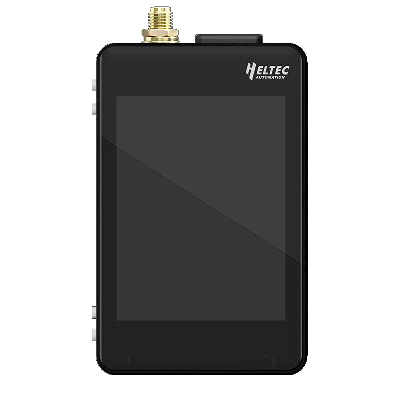


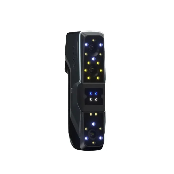
The smartwatch boasts a range of innovative features, including swappable MAC addresses, WiFi network scanning, built-in LiDAR for distance sensing, and the ability to provide real-time temperature, altitude, humidity, pressure, gas resistance, tilt and acceleration readings.

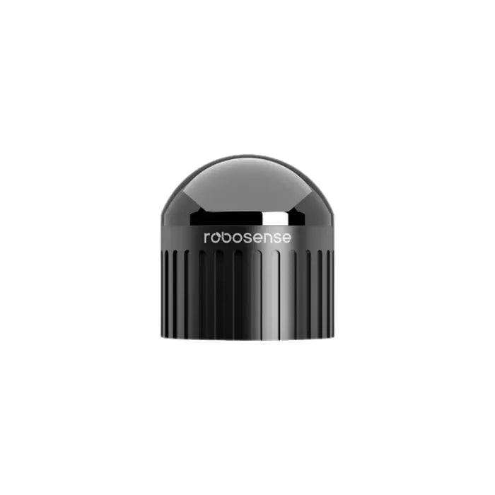
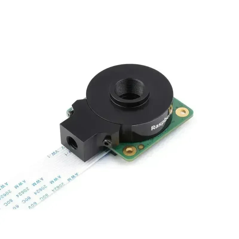
The LiDAR used is a very compact VL53L1X ToF (Time of Flight) distance sensor from STMicroelectronics. It can measure any distance between 4cm and 4 metres with an accuracy of less than ±1%, making it perfect for taking measurements, or if you just want to know how far you are currently from a wall. As it uses a 940 nm laser (infrared and therefore invisible to the human eye), I have also placed a switchable bright red 650nm 5mW laser next to it to assist with aiming or if you are giving a presentation.

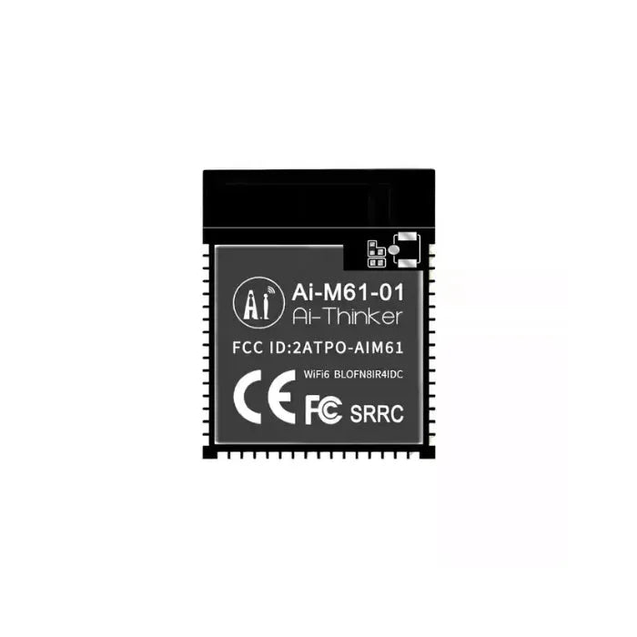
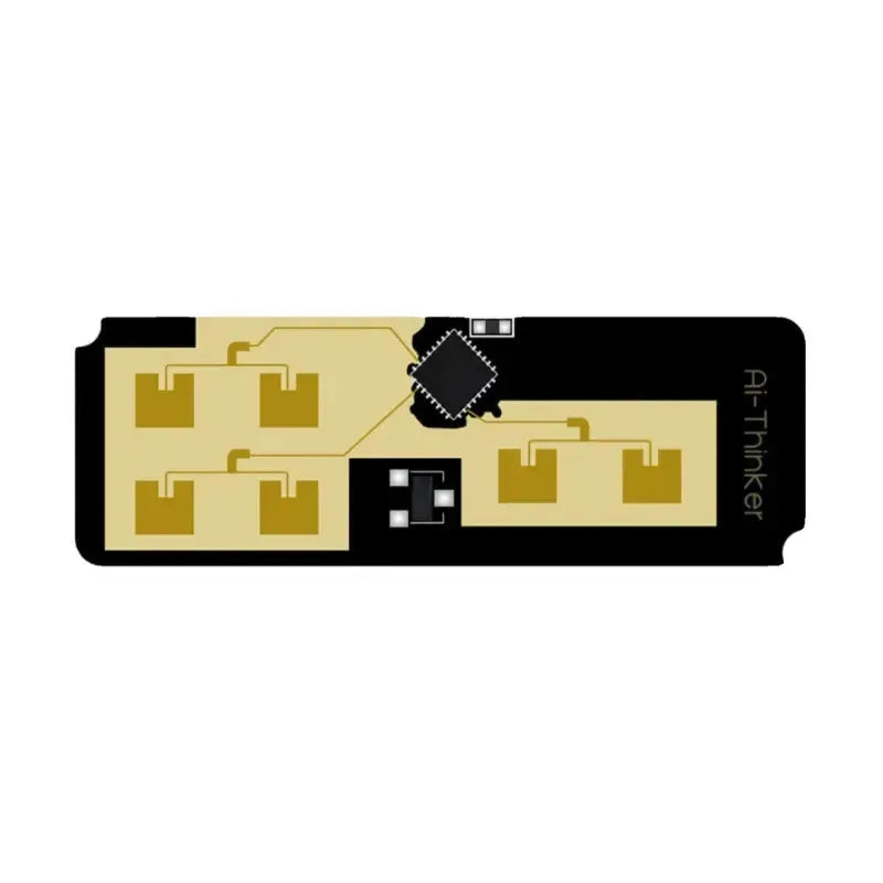
For the wireless portion, the watch utilises ESP-NOW to quickly broadcast data at ultra-low power consumption. This wireless protocol was chosen because of its ability to bypass traditional WiFi connection setups, which makes the action-reaction time between other devices almost instantaneous.

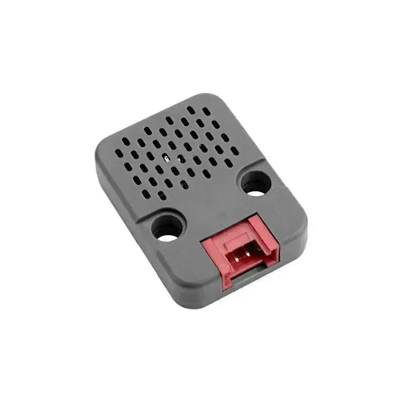
The watch's built-in volatile organic compound (VOC) sensor allows users to monitor and understand atmospheric changes. Simply switch on the watch and observe the IAQ reading change as the target gas comes into contact with the heated metal oxide layer of the BME680. As the sensor also monitors humidity and pressure, it provides a useful reading of current elevation in addition to atmospheric changes. For example, whenever the relative pressure readings in the area where I live are about 10hPa below normal, storms can usually be predicted.

Working Concept
At the heart of all these awesome features is the ESP32-S3-MINI microcontroller or MCU, which handles all communication between the display, various sensors and other wireless devices.

To communicate with these sensors, the MCU utilises I2C (Internal Integrated Circuit), a popular two-wire communication protocol that uses clock and data signals to read and write data from different addressed sensors.

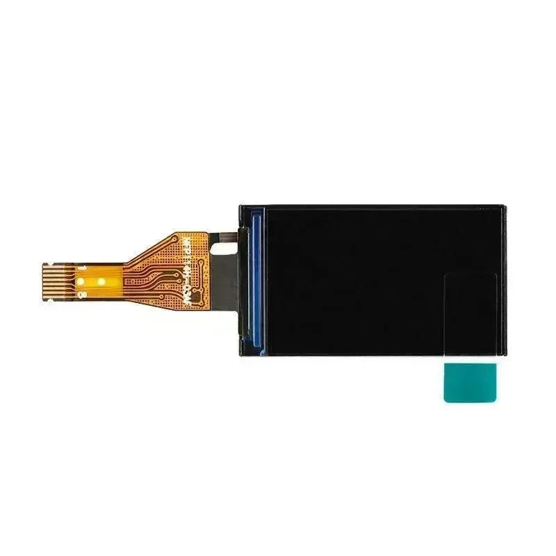
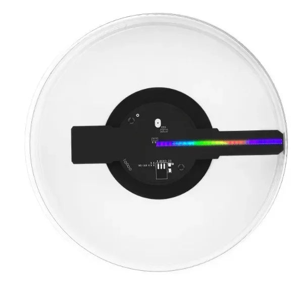
The monitor used for this project is a 280x240 resolution 1.5 inch 262K RGB LCD, perfect for illuminating high resolution images.

Understanding the Hardware
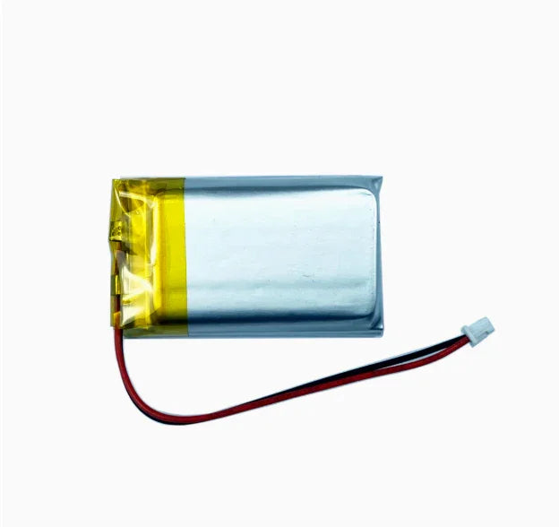
The main circuitry here consists of five sensors (with an optional sixth), a lithium polymer battery charger, a laser module driver, and typical circuitry for powering, communicating, and setting up the ESP32-S3 microcontroller. There are buttons and connectors. Below is the complete schematic:


We can start with the IAQ sensor and the LiDAR. The global labelling of these two sensors is different from the other sensors because they are mounted on a vertical part of the PCB (rather than part of the main circuit board). This is because:
-
LiDAR needs to be perpendicular to the watch in order to point at objects.
-
The further away the BME680 is from other heat-generating components, the more accurate its ambient readings will be.
It should also be noted that the VL53L1X LiDAR works best in low ambient light. I have not experienced any problems using it indoors and it works even better with the lights off. However, when using it on a sunny day, the ambient light from the sun introduces noise into the sensor's measurements, reducing the accuracy and reliability of the distance readings.
In addition, while the laser pointer is used to help aim the LiDAR, it is not always a direct indicator of the measured position.The VL53L1X distance measurement algorithm basically works by taking an area around the centre (about 9.8 degrees in all directions from where you're pointing) in order to get a larger sample of the incident light. It then uses this combined reading to calculate the distance. That is, if you're trying to measure an environment close to a laser dot, then the measured distance will be a combination of the distance in the click + the reading of something nearby (within 9.8 degrees).

Capacitors C5, C8, C7, and C10 are used for decoupling to smooth the power input to the chip. These values are determined by the LiDAR and BME680 datasheets.R1 is used as an additional pull-down resistor to ensure that the LiDAR is disabled when not in use. There are no pull-up resistors on these for I2C communication as the lines are already pulled up in the MCP3427 ADC circuit (for battery monitoring) which we can look at next.

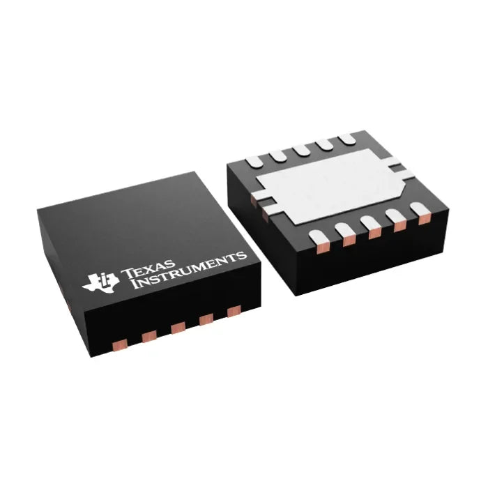
This MCP3427 analogue-to-digital converter (ADC) is very similar to the previous one, as the decoupling capacitor values are determined by the part data sheet. However, in this case the I2C line is pulled up and there is a voltage divider (R13 and R14) on the left side. This voltage divider is important because we want to proportionally reduce the LiPo battery input voltage to a low enough voltage for the ADC to read consistently. Since the battery voltage decreases as it is charged, this reading voltage will give a strong indication of how much power is left in the watch.
More information to follow: LiDAR Distance Sensor and WiFi Scanning