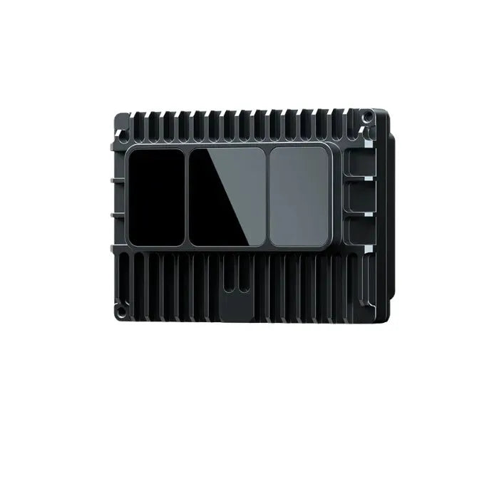
1. What is VL53L0X?

2. Principles
3. Specifications
- Ultra small size: 4.4 x 2.4 x 1.0mm
- Operating voltage: 2.6V-5V DC
- 940 nm infrared light
- Very fast response (50 ms)
- Range: Normal mode 0 - 1000mm, Remote mode 0 - 2000mm
- Deviation of 1% at a distance of 1 meter (more than 10% at a distance of 2 meters)
- Emitted laser light is safe for the eyes and completely invisible
- Communication mode: IIC, 400KHz, device address 0x52, the lowest bit is the read/write flag bit. 0 means write, 1 means read. Therefore, when writing, this 8-bit data is: 0101 0010, i.e. 0x52. When reading, this 8-bit data is: 0101 0011, i.e. 0x53.


4. Pinout & Schematic

- 1 pin AVDDVCSEL: VCSEL power positive
- 2-pin AVSSVCSEL: VCSEL power supply ground
- 3 pins, 4 pins, 6 pins, 12 pins GND: ground
- Pin 5 XSHUT: power mode control, if you don't need the hibernation function, this pin can be directly connected to AVDD.
- Pin 7 GPIO1: Interrupt output. Open-drain output, so must be external pull-up.
- Pin 8 DNC: Dangling
- Pin 9 and 10: IIC communication port
- Pin 11 AVDD: power supply positive

5. Firmware State Machine


When powered up, the VL53L0X enters the Hw Standby state, which is a standby state with very low power consumption. Then pull up the XSHUT pin to put the VL53L0X into Fw Boot state to start preparing for ranging. If the standby state is not needed, you can connect XSHUT to AVDD. the VL53L0X cannot communicate with the IIC when it is in sleep state.
The VL53L0X has 3 operating modes:
-
Single mode: after receiving the range start command, it starts to measure, and automatically exits and enters the Sw Standby state after the measurement is completed.
-
Continuous Mode: After receiving the range start command, it will keep on measuring until it receives the range stop command. When the stop command is received, the last measurement will be completed before exiting.
-
Continuous Interval Mode: After receiving the range start command, it starts to measure, and after completing one measurement, it waits for a period of time before taking the next measurement until it receives the range stop command. The waiting time between measurements is adjustable.
6. Precautions During Use
The VL53L0X is normally used in combination with a coverslip. The coverslip serves two purposes: to provide physical protection from dust and to filter light.

Coverslips are usually opaque and have either two circular holes or one elliptical hole to emit and receive infrared light. Coverslips must meet a number of optical requirements to ensure ranging capability. The quality of the coverslip is measured by the transmission coefficient and the haze coefficient.
There are two parameters to be aware of: the air gap between the VL53L0X and the coverslip window and the expansion area (exclusion area) in front of the VL53L0X, as shown below:

The Ideal Coverslip has the Following Characteristics:
(1) no structural defects in the plastic or glass material
(2) no surface defects that can cause fingerprint light scattering or smudge sensitivity
(3) Transmittance >90% in the near infrared (940nm ± 10nm) and low haze conditions
(4) External coating (anti-fingerprint or anti-reflective coating) that does not reduce fingerprint immunity
(5) Single material. Use of dual materials may alter performance.
The ideal structural design (the structure of a coverslip over VL53L0X) has the following characteristics:
(1) Small air gap (<0.5 mm)
(2) Thin coverslip
(3) Inclination angle between the coverslip and the VL53L0X is less than 2 degrees.
(4) tight tolerances.
Effect of coverslip quality on laser transmission:


7. Calibration Process
-
In order to ensure the accuracy, the user should carry out a calibration after determining his/her usage environment (whether to cover the glass cover, usage environment temperature, power supply voltage, etc.). The process is as follows:

- Temperature calibration is the determination of two temperature-dependent parameters: VHV and phase cal. Recalibration is required each time there is a temperature difference of greater than 8 degrees between the environment in which the VL53L0X is used and the environment in which it is calibrated.
- Offset calibration is the offset between the calibration time distance and the measurement distance, and is generally recommended to be calibrated at 10cm. Offset is generally a fixed value, when the power supply voltage, ambient temperature, whether to add a glass cover, etc., read out the measured value and the actual value of the difference between the offset can be obtained.

-
CrossTalk Calibration: CrossTalk is crosstalk, which is defined as the signal bouncing back from the coverslip. If a glass coverglass is added, when the laser light is shot out of the coverglass, part of the laser light will be reflected back as an interference signal. The size of the interference signal depends on the type of coverslip and the size of the air gap. The size of the distance error produced by the interference signal is proportional to the ratio of the size of the crosstalk to the size of the signal returned from the target.


8.Ranging
- The user can get the data by polling or interrupting
- Ranging process

-
IIC writing 1 byte of data

-
IIC reads 1 byte of data

-
IIC write multiple bytes of data

-
IIC reads multiple bytes of data

 openelab.de
 openelab.com


