openelab.de
 openelab.com


SMD Components Soldering Practice Board DIY Kit with battery pack
Shipping within 72 hours
*Excluding pre-order items
SMD Components Soldering Practice Board DIY Kit with battery pack
Kit Name: SMD Component Soldering Practice Board
Kit Model: SMD-P
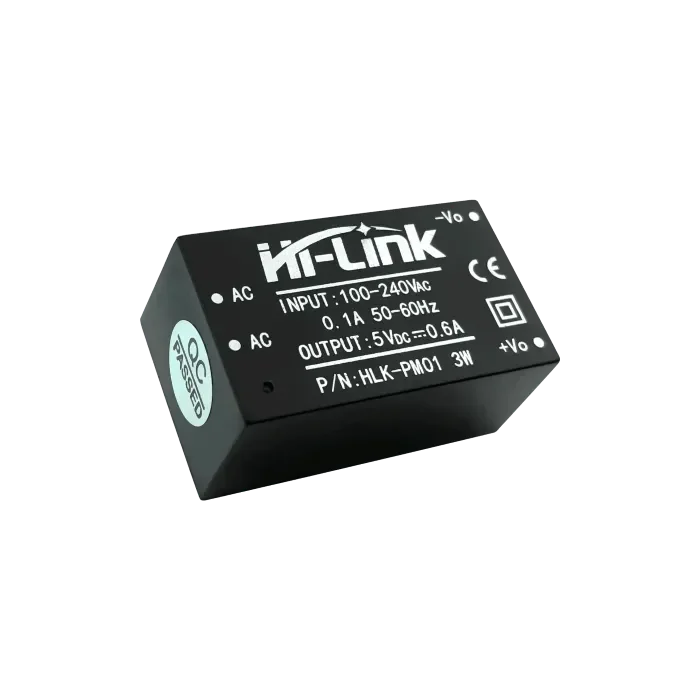
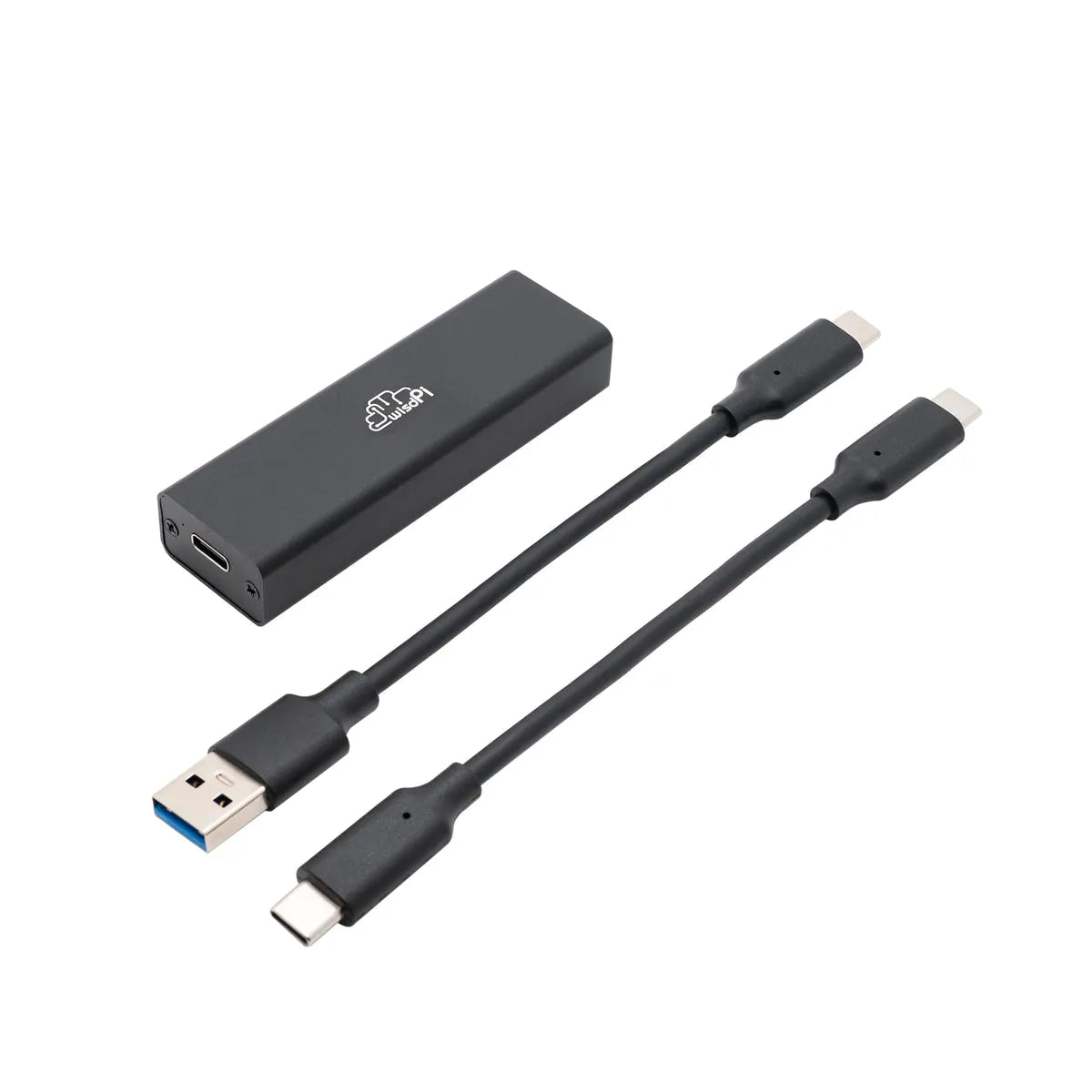
Operating Voltage: 4.5~5V
PCB Thickness: 1.6mm
Dimensions: 91.4*60mm
The SMD-P Soldering Practice Board is divided into two sections: Practice Zone and Practical Zone.
Practice Zone:
The area outside the large circle is the practice zone. Beginners start here to practice soldering. Components can be removed and re-soldered multiple times for further practice. This section includes nine types of components as listed below:
Front-side Components:
- 0805 Resistors ×10
- 0603 Resistors ×14
- 0402 Resistors ×12
- 0805 Capacitors ×10
- 0603 Capacitors ×14
- 1206 Diodes ×6
- SOT-23 Transistors ×6
- 0603 Resistor Networks ×6
Back-side Components:
- SO-8 IC ×1
- SO-16 IC ×1
- QFP44 IC ×2
Practical Zone:
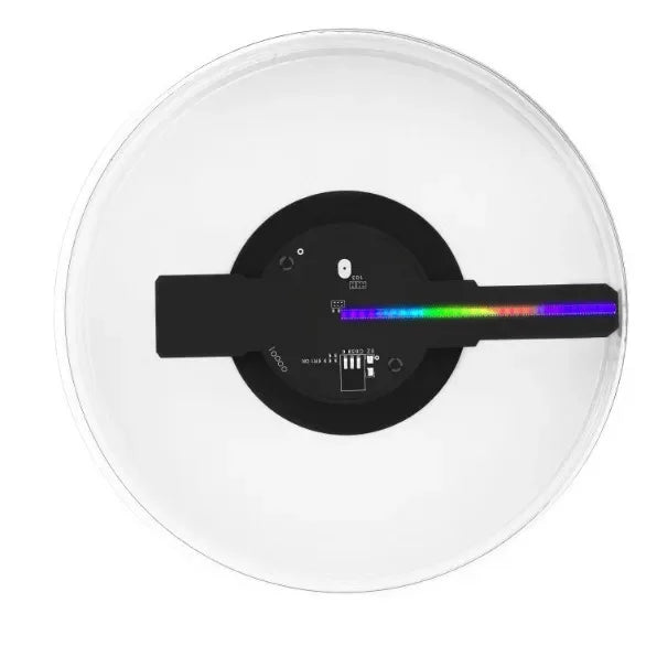
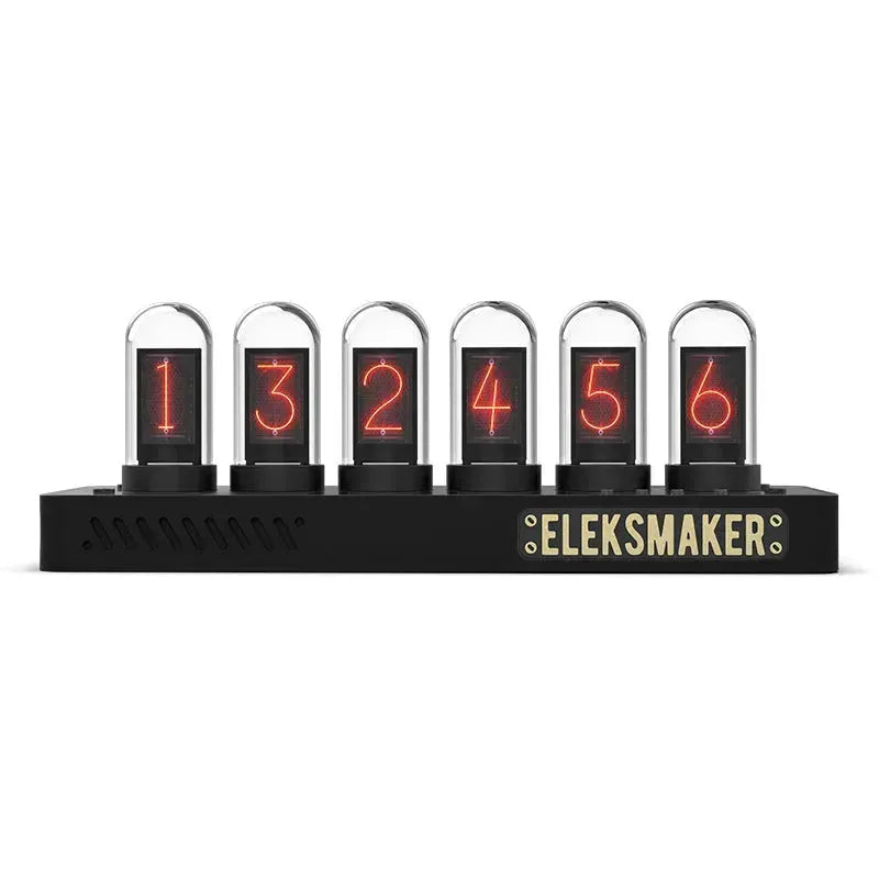
The area inside the large circle serves as the practical zone for testing the soldering results. Once the components are correctly soldered, the board powers on and functions as a lucky wheel. Each LED corresponds to a different animal, adding an element of fun to the project. This section includes six types of components as listed below:
- 0805 Resistors ×3
- 0805 Capacitors ×2
- 0805 LEDs ×10
- 3216 Capacitors ×2
- SOT-23 Transistor ×1
- SO-8 IC ×1
- SO-16 IC ×1
- 6×6×4.5 SMD Switch ×1
Part I: Soldering and Testing in the Practice Zone
-
Solder 10 × 0805 Resistors.
Use a multimeter in ohmmeter mode to measure the resistance between J and J1 to verify the soldering. -
Solder 14 × 0603 Resistors.
Measure the resistance between I and I1 to confirm proper soldering. -
Solder 12 × 0402 Resistors.
Check the resistance between H and H1. -
Solder 10 × 0805 Capacitors.
Use the capacitance mode on a multimeter to test the capacitance between D and D1. If the multimeter lacks capacitance mode, use the ohmmeter mode to ensure the resistance between adjacent pads is zero. -
Solder 14 × 0603 Capacitors.
Measure the capacitance between F and F1 (or use ohmmeter mode if needed). -
Solder 6 × 1206 Diodes (pay attention to polarity).
Measure the forward voltage drop using the diode mode of the multimeter. -
Solder 6 × SOT-23 Transistors.
Use an ohmmeter to measure the resistance from point C to each collector, point E to each emitter, and point B to each base. -
Solder 6 × 0603 Resistor Networks:
- Solder one side of each network, then apply solder to both sides.
- Use an iron to heat the soldered pins and remove excess solder.
-
Verify the Resistor Networks:
- Measure the resistance between K-K1, L-L1, M-M1, and N-N1. The value should match the expected 60K resistance.
- Also, measure K-L, L-M, and M-N; these readings should be infinite. If not, there may be a solder bridge between the pins.
Back-Side IC Soldering:
-
Solder the SO-8 and SO-16 ICs (pay attention to orientation).
Measure the resistance between each IC pin and the test points to confirm soldering. -
Solder 2 × QFP44 ICs (ensure correct orientation).
Similarly, the resistance between adjacent test points is measured to check for solder bridges.
After successfully completing the practice zone soldering, your SMD soldering skills should have improved significantly. Now, let's move on to the practical zone for real circuit soldering to test your skills.
Part II: Soldering in the Practical Zone
- Solder 1 × 0805 Resistor with 470K resistance (marked 474).
- Solder 2 × 0805 Resistors with 1.2K resistance (marked 122).
- Solder 1 × 0805 Capacitor with 10nF (marked 103).
- Solder 1 × 0805 Capacitor with 100nF (marked 104).
- Solder 1 × SOT-23 Transistor (observe polarity).
- Solder 1 × SO-8 IC (with proper orientation).
- Solder 1 × SO-16 IC (with correct orientation).
- Solder 2 × 0805 Capacitors (non-polarized).
- Solder 10 × 0805 LEDs (pay attention to direction).
- Solder 1 × SMD Switch.
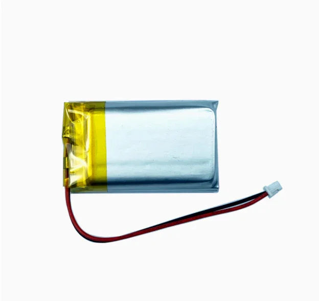
- Solder the Battery Holder Wires (observe polarity).
With the completion of the practical zone soldering, your board is ready for testing. The lucky wheel function will help you verify your soldering results and make the learning process more engaging.
1. General Shipping Information
- We provide reliable shipping services with a tracking number for each order.
- Shipping addresses must be entered in English and should not contain special symbols, so that the courier system can recognize your location correctly.
- Please make sure your shipping address is accurate before placing your order. We ship strictly according to the address provided at checkout.
- In-stock orders are usually dispatched within 1 business day after order confirmation.
- Estimated delivery times refer to the period after dispatch and do not include order processing time, weekends, public holidays, customs inspection, or force majeure delays.
- If you need to cancel or modify your order, please contact us before the order is marked as “Shipped”. Once shipped, the order cannot be canceled or changed.
🚀 Need Faster Shipping?
If you require expedited shipping, please contact our customer support team at info@openelab.io for a customized quote based on your destination.
2. Shipping Rates & Options
Shipping rates are calculated based on order value, destination, and available shipping methods. The final available options will be displayed at checkout.
2.1 Germany Domestic Shipping
| Shipping Method | Order Value | Cost | Est. Delivery |
|---|---|---|---|
| Deutsche Post | €0.00 - €50.00 | €4.95 | 2-4 Business Days |
| Deutsche Post | Over €50.00 | Free | 2-4 Business Days |
|
DHL Paket (Faster Delivery) |
€0.00 - €50.00 | €6.95 | 1-3 Business Days |
|
DHL Paket (Faster Delivery) |
€50.00 - €100.00 | €2.00 | 1-3 Business Days |
|
DHL Paket (Faster Delivery) |
Over €100.00 | Free | 1-3 Business Days |
2.2 Selected EU Countries / Regions
Available EU shipping destinations are shown at checkout based on your shipping address. For orders shipped to selected EU countries or regions outside Germany, we use FedEx Regional Economy.
| Shipping Method | Order Value | Cost | Est. Delivery |
|---|---|---|---|
| FedEx Regional Economy | €0.00 - €100.00 | €7.95 | 3-5 Business Days |
| FedEx Regional Economy | Over €100.00 | Free | 3-5 Business Days |
EU orders may be fulfilled from our Munich warehouse or, when applicable, from our Shenzhen warehouse depending on inventory availability. For EU member states, OpenELAB covers applicable import duties and taxes under DDP service where required.
2.3 United States
| Region | Shipping Method | Order Value | Cost | Est. Delivery |
|---|---|---|---|---|
|
Continental U.S. (50 States) |
USPS Ground Advantage | €0.00 - €45.00 | €4.95 | 3-7 Business Days |
| USPS Ground Advantage | Over €45.00 | Free | 3-7 Business Days | |
| USPS Priority Mail | €0.00 - €45.00 | €16.95 | 1-4 Business Days | |
| USPS Priority Mail | Over €45.00 | €14.95 | 1-4 Business Days | |
|
Non-Continental U.S. (AK, HI, PR, etc.) |
USPS Ground Advantage | €0.00 - €60.00 | €6.95 | 5-9 Business Days |
| USPS Ground Advantage | Over €60.00 | Free | 5-9 Business Days |
Non-Continental U.S. regions include Alaska, American Samoa, Guam, Hawaii, the Marshall Islands, the Northern Mariana Islands, Palau, Puerto Rico, the U.S. Virgin Islands, and U.S. Armed Forces addresses.
2.4 International Destinations Outside the EU
For selected international destinations outside the EU, including Switzerland, the United Kingdom, and Norway, shipping rates are as follows:
| Order Amount | Shipping Cost |
|---|---|
| €0.00 - €300.00 | €19.95 |
| Over €300.00 | Free |
For non-EU destinations, import duties, taxes, and customs fees may be charged by the destination country and are the responsibility of the recipient.
3. Warehouses & Fulfillment
Our products may be stored in our Munich, Arlington, and Shenzhen warehouses. The actual shipping warehouse depends on product availability and destination.
3.1 Munich Warehouse
For products stored in our Munich warehouse, we use Deutsche Post or DHL Paket for domestic deliveries within Germany. For selected EU destinations outside Germany, we use FedEx Regional Economy.
3.2 Arlington Warehouse
For products stored in our Arlington warehouse, we use USPS or UPS for deliveries within the United States.
3.3 Shenzhen Warehouse
For pre-order items or products fulfilled directly from our Shenzhen warehouse, we arrange reliable international shipping based on destination and inventory status. For EU member states, OpenELAB covers applicable import duties and taxes under DDP service where required.
4. Inventory, Pre-orders & Split Shipments
- Inventory Status: Please check the product page for real-time stock information. If an item is out of stock in our local warehouses, it may be marked as “Pre-order”.
- Pre-order Fulfillment: Pre-order items may be shipped directly from Shenzhen or restocked to a local warehouse first before final delivery.
- Split Shipments: If your order contains both in-stock and pre-order items, we may ship them separately. No additional shipping fee will be charged for split shipments caused by our fulfillment arrangement.
5. Customs, Taxes & Delivery Issues
5.1 Customs and Taxes
For EU Member States:
Whether shipped from Germany or China, OpenELAB covers applicable import duties and taxes under DDP service where required. Customers in EU member states should not be charged additional import duties or VAT upon delivery.
For destinations outside the European Union, such as Switzerland, Norway, and the United Kingdom, import duties, taxes, and customs fees may be charged by local authorities upon delivery. These fees are the responsibility of the recipient.
5.2 Damaged, Delayed, or Lost Parcels
Please inspect your parcel upon delivery where possible. If you notice visible damage, please report it to the courier and contact us as soon as possible. This does not affect your statutory consumer rights.
If your parcel is delayed, lost, returned to sender, or the tracking information has not updated for an unusual period of time, please contact us at info@openelab.io. We will assist you in checking the shipment status with the courier.
5.3 Incorrect Address or Failed Delivery
If a parcel cannot be delivered due to an incorrect or incomplete address provided by the customer, refusal of delivery, or failure to collect the parcel, additional shipping or return costs may apply.
6. VAT
For orders within the EU, VAT is collected at checkout according to the applicable destination rules. No additional VAT should be collected upon delivery for EU member state orders covered under our DDP shipping arrangement.