openelab.de
 openelab.com


The I2C Hub 1 to 6 Expansion Unit v2.1 (based on PCA9548AP) and the I2C Hub 1 to 6 Expansion Unit (based on PCA9548APW) are both designed for I2C bus expansion. The main difference between them lies in their configuration methods: the former uses a DIP switch for manual control, making it suitable for fixed setups, while the latter utilizes software-based dynamic switching for greater flexibility.
In contrast, the I/O Hub 1 to 6 Expansion Unit (STM32F0), powered by the STM32F0 microcontroller, offers diverse functionalities such as GPIO, PWM, and ADC, focusing on general I/O expansion. The choice between these units depends on the specific needs of your project, whether it requires dedicated I2C applications or broader I/O management.
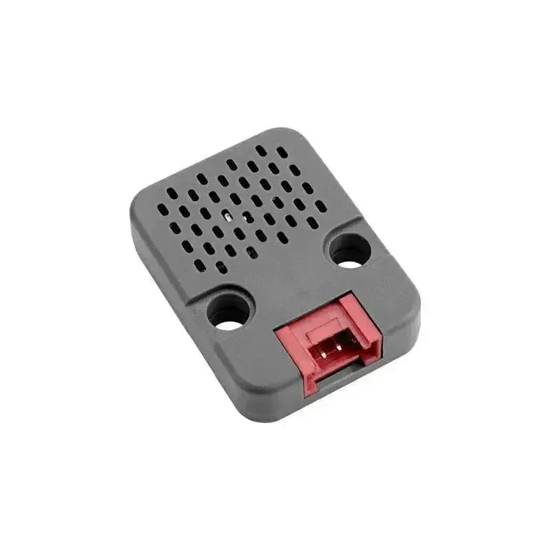
Note: The black ports of M5Stack products are I/O ports and the red ones are I2C ports.

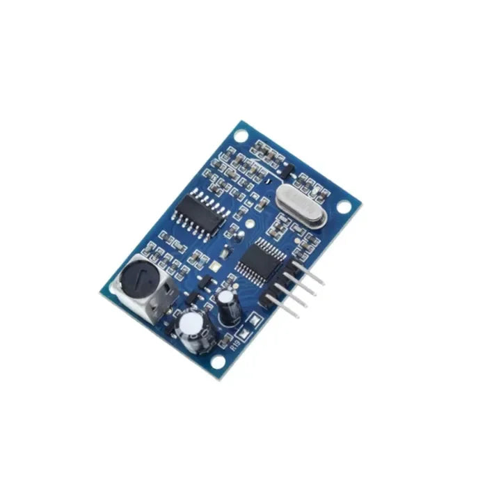
I2C Hub 1 to 6 Expansion Unit (PCA9548APW)
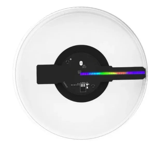
The PaHUB2 unit is an I2C Expandable Hub designed to overcome the limitations of a single I2C interface. It allows the expansion of one I2C HY2.0-4P interface to accommodate up to six additional I2C channels.
By employing polling control on the different channels, the hub allows for the connection of multiple slave devices sharing the same I2C address. This enables better device coexistence by allowing communication on different channels without conflicts.
To enhance its functionality, the PaHUB2 unit incorporates the PCA9548AP I2C multi-channel switch IC, which is integrated within the hub. This switch IC provides the necessary capabilities for seamless switching between the various I2C channels. With the PaHUB2, concerns regarding the insufficiency of I2C interfaces for expansion are alleviated. It presents a convenient and efficient solution for augmenting the I2C capabilities of your system, enabling connection and communication with multiple I2C devices that share the same address.

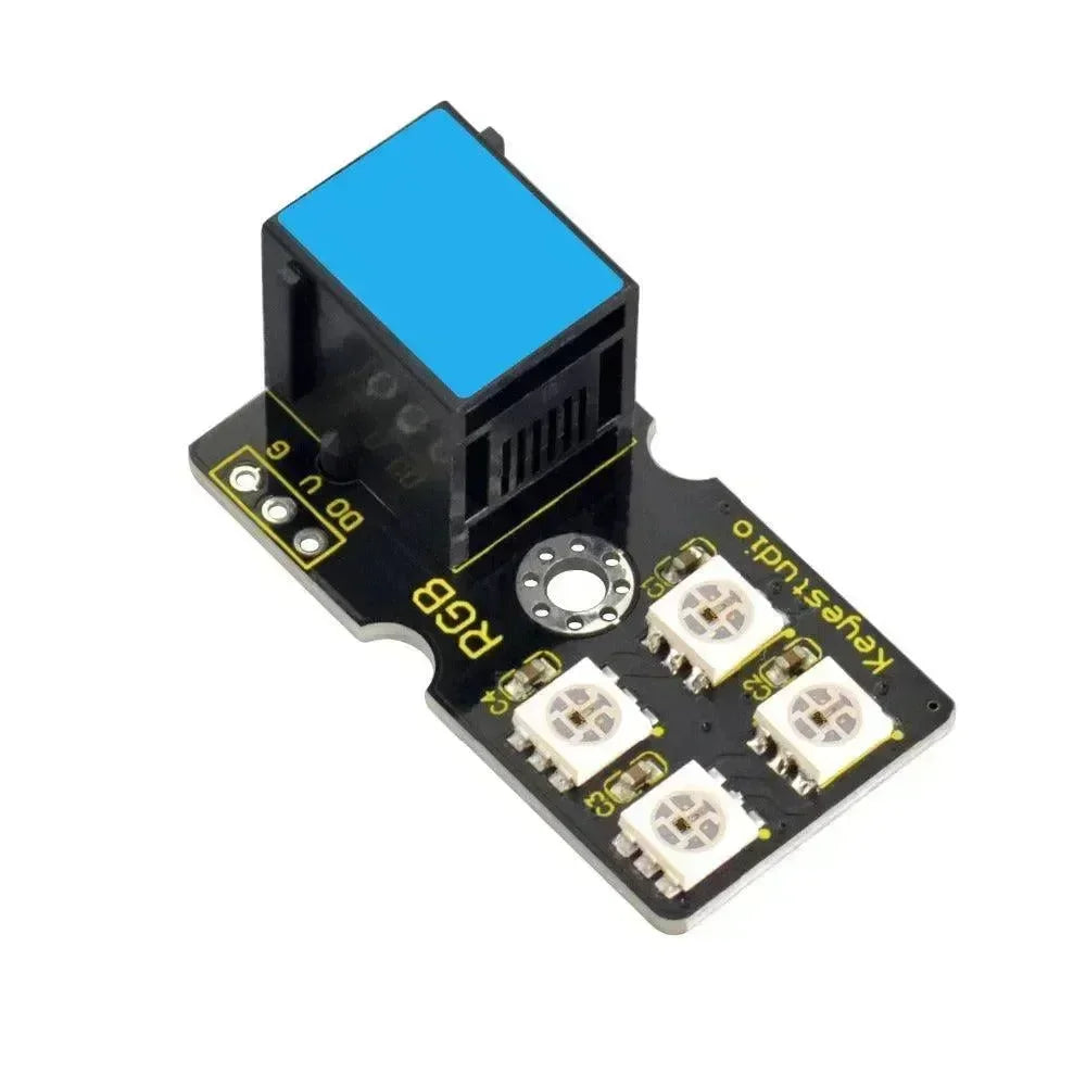
I2C Hub 1 to 6 Expansion Unit v2.1 with DIP Switch (PCA9548A)
The Unit PaHub v2.1 is an I2C multiplexer that utilizes the PCA9548AP chip. It expands a single I2C interface into six channels, allowing multiple devices with the same or different I2C addresses to coexist on the same I2C bus by selecting different channels through channel polling. The module features an onboard DIP switch that makes it easy to adjust the I2C address of the Unit PaHub v2.1, supporting cascading for connecting additional I2C devices. Compared to its predecessor, this unit offers improved flexibility and scalability for using multiple I2C devices in parallel. It is ideal for applications that require the simultaneous operation of multiple I2C devices.
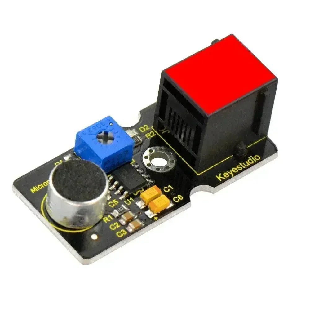
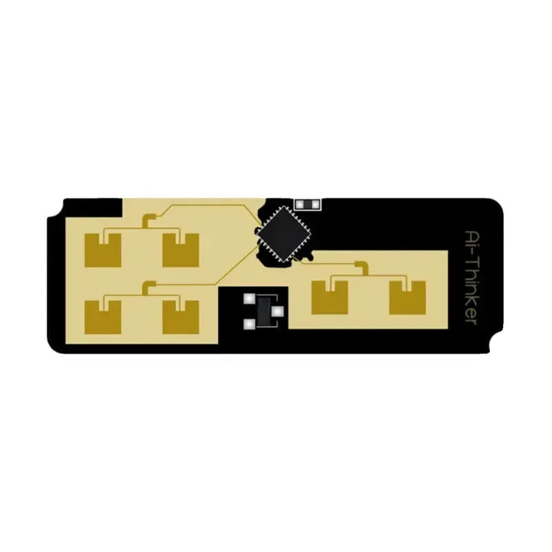
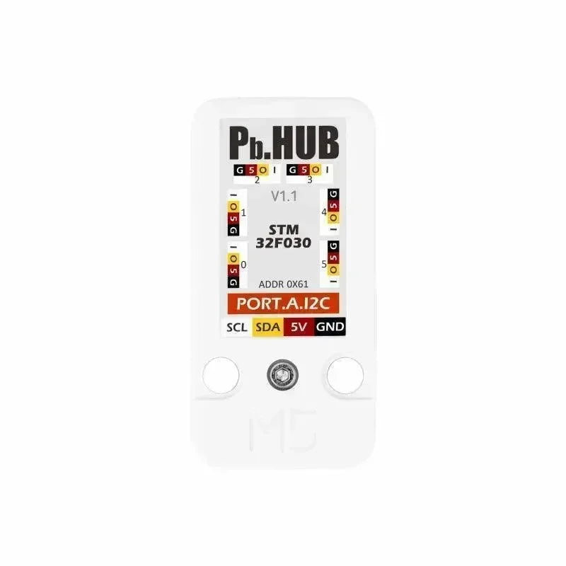
I/O Hub 1 to 6 Expansion Unit (STM32F0)
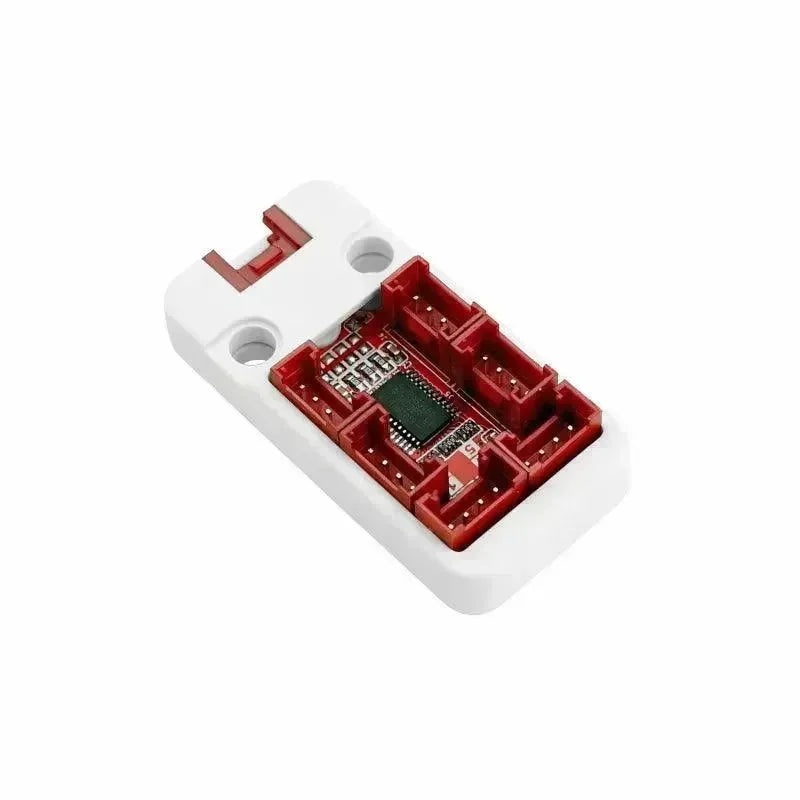
The PbHUB Unit is a versatile 6-channel expansion module designed for seamless integration and efficient control of various functionalities. With I2C compatibility and the STM32F030 microcontroller, it supports GPIO, PWM, servo control, ADC sampling, RGB light management, and customizable functions, making it ideal for robotics, home automation, IoT projects, and more. Its flexibility and wide-ranging applications provide a reliable solution for expanding and managing complex electronic systems.
I2C Hub 1 to 6 Expansion Unit v2.1 VS I2C Hub 1 to 6 Expansion Unit VS I/O Hub 1 to 6 Expansion Unit (STM32F0)
| Specification | I2C Hub 1 to 6 Expansion Unit v2.1 | I2C Hub 1 to 6 Expansion Unit | I/O Hub 1 to 6 Expansion Unit (STM32F0) |
| Chip Solution | PCA9548AP | PCA9548AP | TCA9548A |
| Communication Address | I2C: 0x70~0x77 (adjustable via DIP switch) | I2C: 0x70 (adjustable via A0, A1, A2 resistors) | I2C:0x61(Modified by register) |
| Operating Temperature | 0~40°C | - | - |
| Product Dimensions | 48 × 24 × 12 mm | ||
| Packaging Dimensions | 136 × 92 × 12 mm | 67 × 53 × 12 mm | 136*92*12mm |
| Product Weight (Net) | 7.1 g | 7 g | 6.7g |
| Packaging Weight (Gross) | 12.9 g | 19 g | 11.8g |
-
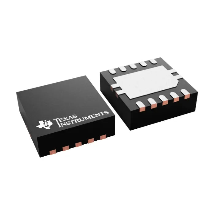
PCA9548A vs. PCA9548APW
- PCA9548A: This is NXP’s standard 1-to-8 I2C multiplexer, frequently used to isolate and manage multiple I2C slave devices, thus preventing address conflicts.
- PCA9548APW: This is a specific package or variant of the PCA9548A. The 'PW' suffix typically indicates package type or certain process-related characteristics, potentially differing in electrical properties or package form.
-
Version and Hardware Features
v2.1 with DIP Switch:
- DIP Switches: The v2.1 version includes DIP switches that allow users to manually select and activate individual I2C channels. This is especially useful in scenarios requiring a fixed hardware configuration for certain I2C devices, avoiding the complexity of software-based settings.
- Hardware Improvements: The v2.1 design may incorporate hardware enhancements such as improved power management, more stable signal transmission, or better noise immunity.
PCA9548APW Version:
- No DIP Switch: This version generally does not include DIP switches. Instead, it relies on software-controlled I2C commands to select and switch channels. This approach offers greater flexibility for dynamic control, making it suitable for applications where I2C channels need to be reassigned based on runtime conditions.
- Packaging and Layout: Since it utilizes the PCA9548APW chip, PCB layout, dimensions, and pin arrangements may differ from the v2.1 version, depending on the manufacturer’s design.
-
Configuration Methods
v2.1 with DIP Switch:
- Manual Configuration: Users can physically set switches to directly control the multiplexer’s channel selection, ideal for applications that don’t require frequent reconfiguration of I2C channels.
- Plug and Play: No software intervention is needed, making it suitable for simple hardware expansion needs.
PCA9548APW Version:
- Software Control: Channel switching is performed via I2C commands, perfect for complex applications that need dynamic I2C channel management based on varying conditions.
- High Flexibility: Channels can be changed on the fly, offering greater adaptability for projects requiring more sophisticated configurations.
-
Application Scenarios
v2.1 with DIP Switch:
- Ideal for projects with fixed I2C device configurations, such as development board expansions or prototyping.
- Suitable for users who want a straightforward, hardware-based method of selecting I2C channels without the need for complex software control.
PCA9548APW Version:
- Well-suited for complex systems that need dynamic I2C device management, such as multi-sensor networks or embedded systems requiring frequent device switching.
- Enables more flexible channel assignments through software, accommodating diverse and changing requirements.
Power and Compatibility
- Voltage Requirements: Both versions generally support similar operating voltages (e.g., 3.3V or 5V), but specifics depend on the chosen chip variant and manufacturer’s design. Consult the product datasheet before use.
- Compatibility: Both are compatible with standard I2C protocols, but due to different hardware implementations, certain details—like pull-up resistor values or signal integrity—may vary. Choose the appropriate version based on the application’s requirements.
Other Considerations
- Size and Packaging: Select the version that best fits your project’s physical space constraints. The v2.1 version may be slightly larger due to the DIP switches.
- Manufacturer Support: Different versions may be produced by different manufacturers. Reviewing technical support options and community resources can help you make better use of the module.
FAQs
Q1: What is an I2C hub?
A1:
An I2C hub is a hardware module designed to expand and manage an I2C bus, allowing multiple devices to connect to a single master. It addresses challenges such as address conflicts and signal degradation. The hub provides several channels, often utilizing active chips, which enables devices with identical addresses to coexist by isolating them on separate channels.
I2C hubs improve signal integrity, support dynamic device selection, and enhance scalability. This makes them well-suited for applications such as sensor networks, embedded systems, Internet of Things (IoT) projects, and debugging. By simplifying device management and ensuring reliable communication, I2C hubs are essential components in complex electronic systems.
Q2: What are the benefits of having multiple slave device channels on an I2C bus?
A2:
I2C bus support for multiple slave device channels brings several important benefits that are especially valuable in embedded systems and Internet of Things (IoT) projects:
-
Resolve Address Conflicts
-
The I2C protocol has a limited number of slave addresses, which can lead to address conflicts when multiple devices, such as sensors, share the same default address.
-
Multi-channel designs, such as those using multiplexers, allow devices with the same addresses to be assigned to different channels. This approach prevents conflicts and enables more devices to connect to the same I2C bus.
-
Support More Slave Devices
-
While I2C allows for 128 addresses in a 7-bit space, electrical limitations such as signal integrity and pull-up resistance often reduce the number of devices that can be connected.
-
Increasing the number of slave channels on the I2C bus, such as through I2C multiplexers, significantly enhances the number of devices that can be connected, improving the scalability of the system.
-
Improve Communication Efficiency
-
Distributing devices across different channels allows them to avoid occupying the bus at the same time, which helps to reduce interference and congestion.
-
Using multiple channels enhances communication efficiency and improves data transfer stability, particularly for devices that require low latency and high reliability.
-
Flexible Device Grouping and Management
-
Multi-channel I2C allows logical grouping of devices, such as:
-
One channel for environmental sensors (e.g., temperature, humidity, pressure).
-
One channel for display modules (e.g., OLED screens, LCDs).
-
One channel for storage devices (e.g., EEPROM, FRAM).
-
This grouping simplifies development, debugging, and enhances system modularity and maintainability.
-
Isolate Faulty Devices
-
A faulty device (e.g., due to a short circuit or hardware issue) on the I2C bus can block the entire bus.
-
Multi-channel designs prevent faulty devices from impacting other channels, enhancing system reliability and fault tolerance.
-
Enhance Signal Integrity
-
Multi-channel designs minimize issues such as signal loss, crosstalk, and interference caused by connecting too many devices to one bus.
-
Each channel can connect to specific devices, preventing bus overload, enhancing signal quality, and ensuring dependable data transmission.
-
Support Dynamic Device Switching
-
Using multiplexers allows for software-based dynamic channel switching, enabling access to various slave devices as needed.
-
This adaptive switching method is ideal for applications that require real-time access to multiple devices, including multi-sensor data collection and industrial control systems.
-
Simplify Hardware Design
-
Multi-channel I2C reduces wiring complexity in hardware design, removing the necessity for a separate bus for each device.
-
This method lowers development costs and conserves PCB space, making it suitable for compact and budget-sensitive applications.
Q3: How many I2C devices can be connected?
A3:
The number of I2C devices that can be connected to a single bus depends on several factors, including the addressing scheme, electrical limitations, and the use of hardware like multiplexers. With a standard 7-bit I2C address, up to 112 usable device addresses are available, while 10-bit addresses can support up to 1,024 addresses. However, practical limitations imposed by electrical factors, such as bus capacitance (which has a maximum of 400 pF) and the strength of pull-up resistors, generally restrict the number of devices to between 5 and 20 on a single bus. By using multiplexers, such as PCA9548A, this limitation can be significantly expanded. Multiplexers can isolate devices across multiple channels, enabling the connection of hundreds or even thousands of devices in large-scale systems.
Q4: How many I2C devices can be connected?
A4:
To increase the distance of an I2C bus, you can reduce the clock speed to lower signal timing requirements, use lower-value pull-up resistors to strengthen signal integrity or implement I2C bus extenders like the P82B715 or PCA9600 to amplify signals and compensate for capacitance. Adopting differential signaling with modules like PCA9615 helps reduce noise over long distances, while shielded or twisted-pair cables minimize electromagnetic interference. Using I2C multiplexers or repeaters divides the bus into shorter segments or regenerates signals to maintain reliability. For very long distances, consider switching to protocols like RS-485 or CAN, which are better suited for such scenarios.