openelab.de
 openelab.com


What are they?
Getting started
simple factory program
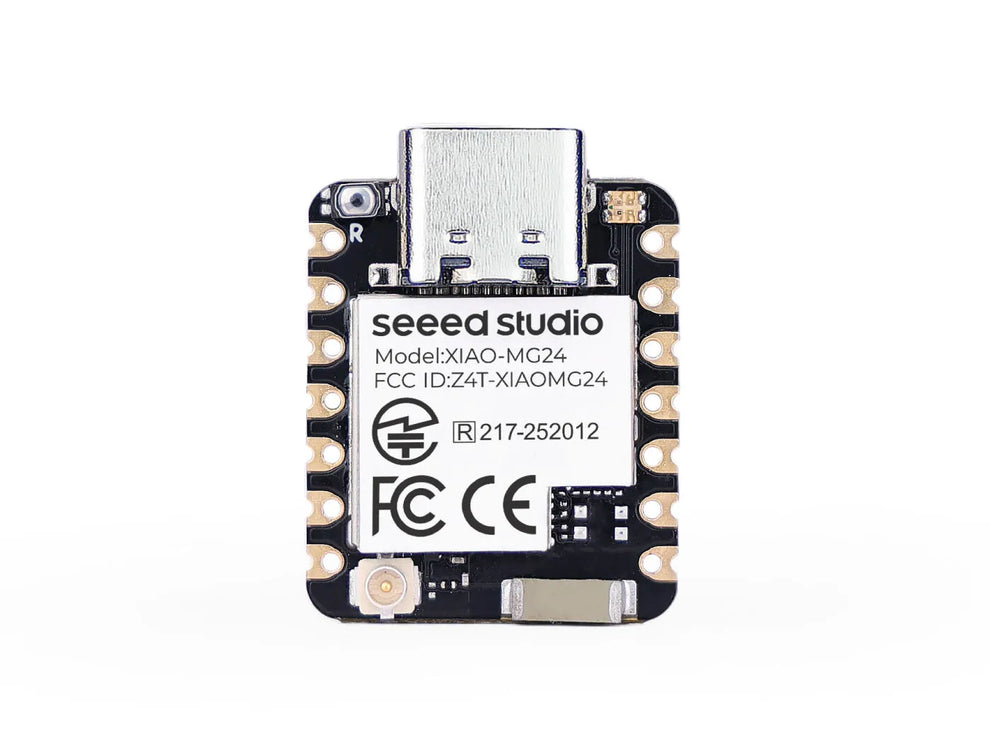
XIAO MG24

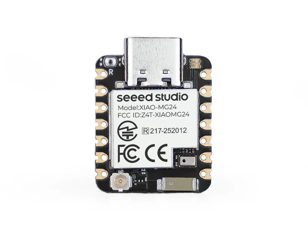
XIAO MG24 Sense

Hardware Preparation
-
1 x Seeed Studio XIAO MG24
-
1 x Computer
-
1 x USB Type-C cable
Software Preparation
-
Step 1. Download and Install the stable version of Arduino IDE according to your operating system.
-
Step 2. Launch the Arduino application.
-
Step 3. Add the XIAO MG24 on-board package to the Arduino IDE and click OK.
-
Step 4. Close the Arduino IDE and reopen it.
Add the XIAO MG24 Board


Begin Your First Blink Program
-
Step 1. Launch the Arduino application.
-
Step 2. Navigate to File > Examples > 01.Basics > Blink, open the program.

-
Step 3. Choose the XIAO MG24 board model and select the appropriate port number to upload the program.


Battery Usage
Battery Connection and Management

Charging status display
-
Without a battery connected: The red light turns on when the Type-C cable is connected and automatically turns off after 30 seconds.
-
Charging with a battery connected: The red light flashes while the Type-C cable charges the battery.
-
When the battery is fully charged: The red light turns off, signaling the completion of the charging process.

Other notes
-
Use Qualified Batteries: Only use batteries that meet the specified requirements.
-
Data Cable Connection: The XIAO can be connected to your computer via a data cable while running on battery power. Rest assured that it has a built-in circuit protection chip for safety.
-
LED Indicator: When powered by a battery, the XIAO MG24 will not show any LED lights (unless you’ve programmed it to do so). Please do not assess whether the XIAO MG24 is functioning based on the LED status; rely on your program for proper evaluation.
-
Battery Level Monitoring: Unfortunately, we currently cannot provide a way to check the remaining battery level through software (due to the lack of available chip pins). You should charge the battery regularly or use a multimeter to monitor the battery level.
Battery Voltage Measurement
Software code:
|
/* Reads an analog input on pin 0, prints the result to the Serial Monitor. This example code is in the public domain. https://www.arduino.cc/en/Tutorial/BuiltInExamples/AnalogReadSerial // the setup routine runs once when you press reset: void loop() { |
Display Result

Deep Sleep and Sleep Example
Demo1 Sleep Mode and wake-up
|
The example shows the basic usage of the Arduino Low Power library by putting the device to sleep for a period of time. This example is compatible with all Silicon Labs Arduino boards. Author: Tamas Jozsi (Silicon Labs) #include "ArduinoLowPower.h" void setup() void loop() Serial.printf("Going to sleep at %lu\n", millis()); |
Demo2 Deep Sleep Mode and wake-up
|
/* The example shows the basic usage of the Arduino Low Power library by putting the device into deep sleep. This example is compatible with all Silicon Labs Arduino boards. Author: Tamas Jozsi (Silicon Labs) #include "ArduinoLowPower.h" void setup() void loop() Serial.printf("Going to deep sleep for 10s at %lu\n", millis());
|
Demo3 Deep Sleep Mode with flash and wake-up
|
/* The example shows the basic usage of the Arduino Low Power library by putting the device into deep sleep. This example is compatible with all Silicon Labs Arduino boards. Author: Tamas Jozsi (Silicon Labs) #define CS_PIN PA6 #define READ_DATA 0x03 void sendSPI(byte data) { void writeEnable() { void setup() pinMode(CS_PIN, OUTPUT);
//Serial.println("Deep sleep timed wakeup"); void loop() //Serial.printf("Going to deep sleep for 10s at %lu\n", millis()); |

Protecting XIAO MG24 from Bricking When in Deep Sleep
1.Use the Escape Pin (PC0)
-
Connection: Connect PC0 to GND before resetting the device.
-
Upload: After resetting, upload your sketch while the device is in the loop.
2.Modify Your Sketch
|
#define USER_SW PC3 // Example pin for user switch void setup() { pinMode(USER_SW, INPUT_PULLUP); |
3.Avoid Unnecessary Flash Sleep
Solutions for Serial Port Access and Recovery
Windows Solutions
1.Download the provided ZIP file.
2.Connect the XIAO MG24
3.Run the Script
4.Verify Recovery
macOS Solutions
1.Download the provided ZIP file.
2.Connect the XIAO MG24
3.Allow Terminal Access
-
Open System Preferences: Go to System Preferences on your Mac.
-
Navigate to Security & Privacy: Click on Security & Privacy, then go to the Privacy tab.
-
Check Accessibility: Under the Accessibility section, ensure that Terminal is allowed to control your computer.
-
Add Terminal if Necessary: If Terminal is not listed, click the + button to manually add it. Select Terminal from your Applications folder.
4.Run the Script
-
Open Terminal.
-
Navigate to the extracted folder using the cd command. For example:
-
Run the script using ./xiao_mg24_erase.sh.This will erase the flash memory and reset the device.
5.Verify Recovery
Note
Other information
FAQ