openelab.de
 openelab.com




















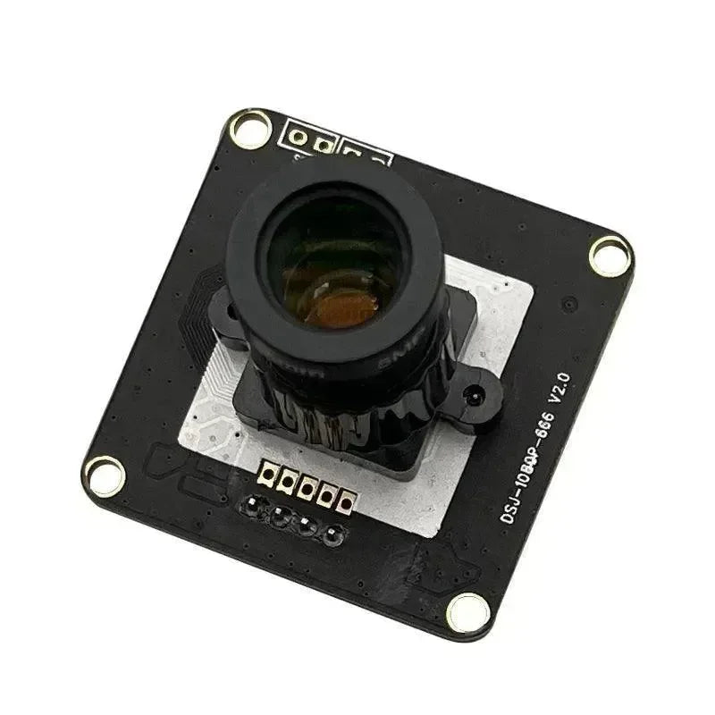













Choose LiDAR when your robot needs route-scale localization, broad geometric coverage, or operation in low-texture spaces.
Choose an RGB-D or depth camera when dense near-field geometry, visual features, or object-level perception matters more. Use both only when one sensor cannot cover the global and close-range requirements.
Selection Focus
- 2D LiDAR: Start here for flat indoor navigation and a ROS 2 stack built around a 2D occupancy map.
- 3D LiDAR: Choose it when ramps, curbs, overhangs, uneven ground, or full-height geometry affect localization or safety.
- RGB-D or depth camera: Choose it for manipulation, docking, shelf or pallet perception, low-obstacle detection, and visual features.
- LiDAR plus RGB-D: Combine them when the robot needs wide-area localization and dense, color-aware perception near the chassis or workspace.
The correct choice is therefore not “the sensor with the most data.” It is the sensor whose coverage, failure modes, ROS messages, and compute load fit the map and navigation stack you intend to build.
LiDAR vs Depth Camera Decision Matrix
Make the architecture decision before comparing individual products. This matrix connects the operating problem to the ROS 2 data path and a practical starting stack.
| Sensor architecture | Best fit | Main limitation | Typical ROS 2 data path | Practical starting stack |
|---|---|---|---|---|
| 2D LiDAR | Flat indoor routes, warehouse AMRs, AGVs, and 2D occupancy-grid navigation | A single scan plane cannot describe obstacles that pass above or below that plane | Driver → sensor_msgs/msg/LaserScan + TF and odometry |
SLAM Toolbox for mapping or localization, with Nav2 handling navigation |
| 3D LiDAR | Uneven terrain, ramps, curbs, overhangs, outdoor routes, and full-height geometry | Higher point-cloud bandwidth, compute load, storage demand, and timing complexity | Driver → sensor_msgs/msg/PointCloud2 + TF; many 3D stacks also use sensor_msgs/msg/Imu
|
3D Cartographer or a LiDAR-inertial pipeline validated for the driver’s point fields |
| RGB-D or depth camera | Near-field perception, manipulation, docking, shelf inspection, and color-aware scene understanding | Forward-facing coverage plus lighting, texture, material, motion-blur, and bandwidth constraints | Driver → depth and RGB Image + CameraInfo; optional PointCloud2 and IMU streams |
RTAB-Map for a configured RGB-D workflow; use a scan converter only when a 2D projection is acceptable |
| LiDAR plus RGB-D | Robots that need route-scale localization, near-field coverage, and semantic perception | Extrinsic calibration, common timing, bandwidth, compute load, and duplicated obstacle data |
LaserScan or PointCloud2 + images + CameraInfo + TF; IMU or odometry as required |
Keep one primary localization stack, then add the second sensor to the costmap or perception layer with a defined role |
Pro Tip: Two sensors that both publish PointCloud2 are not automatically interchangeable. Field names, timestamps, coordinate frames, scan pattern, range, and algorithm expectations still determine compatibility.
What Does a SLAM Sensor Actually Provide?
SLAM estimates the robot’s pose while building or updating a map. The sensor supplies observations; odometry, matching, optimization, and loop closure determine how those observations become a usable trajectory and map.
Odometry estimates short-term motion, mapping places observations in a common frame, and loop closure corrects accumulated drift. Neither LiDAR nor RGB-D prevents drift by itself; calibration, timing, motion, scene structure, and the selected algorithm still matter.
How LiDAR SLAM Works
LiDAR SLAM aligns consecutive scans or point clouds to estimate motion, then optimizes the accumulated trajectory and map. A 2D system often matches planar LaserScan messages against an occupancy grid. A 3D system registers PointCloud2 data and may tightly couple the LiDAR with an IMU.
LiDAR is attractive for navigation because distance measurements directly describe walls, shelves, vehicles, and terrain. It does not need visible color or texture to measure geometry. That helps in dark corridors, plain warehouses, and routes with repeated visual appearance, although repetitive geometry can still make localization difficult.
2D LiDAR vs 3D LiDAR for SLAM
2D LiDAR is a practical choice for flat indoor floors where walls and obstacles intersect a fixed scan plane. It usually produces less data and works naturally with occupancy-grid navigation. This LaserScan-oriented workflow integrates naturally with 2D occupancy-grid navigation.
3D LiDAR adds height information for ramps, curbs, low obstacles, overhangs, vegetation, and uneven ground. It provides richer data but increases bandwidth, compute, storage, and calibration demands. A 3D sensor is not automatically better for every AMR; choose it when vertical structure changes the robot’s safety or localization problem.
LiDAR limitations in real environments
LiDAR can struggle with transparent glass, mirrors, highly reflective metal, very dark materials, rain, fog, dust, and surfaces viewed at difficult incidence angles. A wide range specification also depends on target reflectivity and ambient conditions. The LiDAR blind-spot and sensor-fusion guide covers these failure modes in more detail.
How Depth Camera and RGB-D SLAM Work
A depth camera estimates the distance to many pixels inside a forward-facing image. An RGB-D camera combines that depth map with color, allowing the SLAM stack to use visual features, dense local geometry, or both. The result is especially useful when the robot must recognize objects and understand surfaces as well as avoid them.
Active stereo vs passive stereo
Passive stereo compares two camera views and calculates depth from disparity. It needs enough visible texture for reliable matching. Active stereo projects infrared structure into the scene to improve correspondence on plain surfaces, but strong sunlight can reduce the contrast of that projected pattern.
The Orbbec Gemini 335 supports active and passive stereo, so it can operate across a wider set of lighting conditions than a passive-only design. Real performance still depends on exposure, target material, distance, motion blur, and whether the active pattern remains visible.

An RGB-D camera provides a forward depth field plus image data for visual features, local geometry, and semantic perception.
Where depth cameras are strongest
Depth cameras are valuable for close-range obstacle detection, docking, pallet and shelf perception, bin picking, human interaction, and manipulation. Dense depth reveals the local shape of objects that a sparse or single-plane LiDAR scan may miss. RGB also supports segmentation, classification, fiducial detection, and scene understanding.
The main constraints are coverage and environment. A forward camera does not see behind the robot, and active infrared depth can lose quality outdoors. Fast rotation can add motion blur to visual features, while low-texture or repetitive scenes can weaken visual odometry.
LiDAR SLAM vs Visual SLAM vs RGB-D SLAM
These terms describe related but different pipelines. LiDAR SLAM aligns laser ranges or point clouds. Visual SLAM estimates motion and structure from monocular or stereo images. RGB-D SLAM adds per-pixel depth to the visual stream, reducing scale ambiguity and providing direct local geometry.
| SLAM approach | Main input | Strength | Common weak point |
|---|---|---|---|
| 2D LiDAR SLAM | LaserScan + odometry | Efficient planar mapping and navigation | Cannot describe full vertical geometry |
| 3D LiDAR-inertial SLAM | PointCloud2 + IMU | Rich geometry and motion estimation in 3D | Higher compute, bandwidth, and calibration burden |
| Monocular visual SLAM | Single RGB camera, often with IMU | Low sensor mass and rich appearance features | Scale, lighting, texture, and motion blur |
| Stereo visual SLAM | Synchronized stereo images | Metric depth from camera baseline | Needs texture and stable stereo calibration |
| RGB-D SLAM | RGB + depth + camera calibration | Dense near-field geometry with visual features | Range, sunlight, bandwidth, and camera FOV |
Eight Engineering Factors That Change the Decision
1. Range and field of view
Wide field of view helps a SLAM system retain geometric overlap while the robot turns. Long range gives the planner more reaction distance at speed. A 360-degree LiDAR observes around the chassis, while a single depth camera usually sees only the space in front of its lens.
2. Point density and spatial detail
A 3D LiDAR distributes points across a broad environment. A depth camera can produce much denser samples inside a smaller frustum. For global mapping, broad coverage may matter more than local density; for grasping or low-obstacle detection, dense local depth can be more useful.
4. Glass, reflective metal, and black materials
Both modalities have material-dependent failure cases. Test windows, mirrors, polished floors, shrink wrap, black plastic, and angled metal surfaces using the intended mounting position. A datasheet range measured on a cooperative target cannot predict every surface on a factory route.
5. Robot speed and motion blur
Visual pipelines can lose features during rapid rotation, vibration, or long exposure. LiDAR also needs motion compensation because a rotating or non-repetitive scan is collected over time. An IMU, accurate timestamps, and rigid mounting become more important as speed rises.
6. Compute and interface bandwidth
Dense RGB-D streams can consume substantial USB bandwidth and host memory. Large 3D point clouds also require filtering, registration, and storage. Evaluate the full pipeline at the desired frame rate, including visualization, neural inference, logging, and navigation—not only the sensor driver.
7. Power, weight, and environmental protection
Small indoor robots may value a lightweight USB camera. Outdoor platforms may value a sealed LiDAR and a wider temperature range. Include cables, connectors, mounting brackets, cleaning access, and protective windows in the mechanical budget.
8. Calibration and time synchronization
SLAM quality depends on the transform between the sensor and robot base, plus synchronization between LiDAR, camera, IMU, and wheel odometry. A few milliseconds of timing error can become a visible spatial offset when the robot moves quickly. Multi-sensor fusion also requires accurate extrinsic calibration between every sensing frame.
ROS 2 SLAM Algorithms and Sensor Compatibility
A sensor driver publishes messages; a SLAM package consumes a specific subset of them. Check both sides of that interface before choosing hardware.
| Software | Typical driver output | Algorithm input | Conversion or caveat |
|---|---|---|---|
| SLAM Toolbox | Native 2D LiDAR: LaserScan. A depth camera may publish depth Image + CameraInfo; a 3D sensor may publish PointCloud2. |
sensor_msgs/msg/LaserScan and a valid TF path from the configured odometry frame to the robot base frame |
It does not consume raw RGB-D images or PointCloud2. Use depthimage_to_laserscan or pointcloud_to_laserscan only if the projected 2D view fits the navigation problem. |
| Cartographer |
LaserScan, MultiEchoLaserScan, or PointCloud2; IMU and odometry may also be available |
The configured number and type of range-data topics; Imu and Odometry according to the Lua configuration |
IMU is optional in 2D and required in 3D. Odometry is optional in both. Topic counts and names must match the configuration. |
| RTAB-Map ROS 2 | Synchronized RGB-D or stereo images and camera calibration; configured setups can also use laser scans or 3D point clouds | Inputs depend on the selected RGB-D, stereo, scan, point-cloud, odometry, and synchronization configuration | Do not assume every RTAB-Map launch file consumes every stream. Match the driver topics, synchronization policy, calibration, odometry source, and launch configuration. |
| ORB-SLAM3 | Monocular, stereo, or RGB-D images; optional IMU in supported visual-inertial modes | Synchronized image streams plus camera calibration; IMU for the selected inertial mode | The upstream repository’s bundled ROS examples were tested with ROS Melodic. A ROS 2 deployment normally depends on a separate wrapper, port, or custom integration. |
| LIO-SAM |
PointCloud2 + Imu; optional GPS-related data in supported configurations |
Point cloud with per-point timing and ring or channel data, plus correctly aligned IMU measurements | The upstream implementation directly targets mechanical LiDAR data. Other scan patterns, including Livox workflows, require verified driver formatting and code or configuration changes; they are not plug-and-play. |
Warning: Nav2 is not a SLAM algorithm. It consumes mapping or localization results and uses configured observation sources for its costmaps. Treat SLAM, localization, obstacle perception, and path planning as separate interfaces.
Before recording a long bag, inspect the actual topic types, frame IDs, timestamps, QoS profiles, and publication rates. A correct sensor specification cannot compensate for a broken TF tree or unsynchronized inputs.
Best Sensor Choice by Robot Application
Warehouse AMR and AGV
A 2D LiDAR can be enough for a structured, flat warehouse with stable wall and rack geometry. Add a depth camera when pallets, forks, low obstacles, people, or docking targets require denser near-field perception. Use 3D LiDAR when slopes, suspended obstacles, mixed indoor-outdoor routes, or full-height geometry affect safety.
Outdoor inspection rover
3D LiDAR is usually the stronger primary sensor because range, lighting independence, vertical structure, and environmental sealing matter. A depth camera can add close inspection and visual classification, but direct sunlight and weather protection require careful validation.
Service and delivery robot
Indoor service robots often benefit from a layered design: LiDAR or another wide-area ranging sensor for localization, plus an RGB-D camera for people, low obstacles, doors, elevators, and docking. A camera-only design can work on short, controlled routes but needs robust visual features and coverage planning.
Manipulator and mobile manipulator
Dense RGB-D data is usually more valuable at the arm workspace because grasping and placement depend on local surface geometry and object identity. The mobile base may still use LiDAR for navigation. This separates the global-map problem from the hand-eye perception problem.
Drone and legged robot
Weight, vibration, rapid rotation, and six-degree-of-freedom motion make inertial fusion critical. A 3D LiDAR-inertial or visual-inertial pipeline can work, but mounting stiffness, IMU calibration, time synchronization, and motion compensation often decide performance more than the sensor label.
When to Combine LiDAR and a Depth Camera
Fusion is justified when the robot needs capabilities that do not fit inside one sensing envelope. LiDAR can maintain a stable global geometric map, while a forward or downward RGB-D camera detects low obstacles, supplies dense near-field depth, and adds color for semantic perception.
A useful architecture separates responsibilities:
- LiDAR: global localization, mapping, route-scale obstacle geometry, and long-range awareness.
- Depth camera: near-field free space, docking, steps and low obstacles, object geometry, and RGB semantics.
- IMU and wheel odometry: short-term motion constraints between perception updates.
- Fusion layer: transforms observations into a common base frame and handles confidence, timestamps, and failure cases.
Warning: More sensors do not automatically create a better map. Poor extrinsic calibration, inconsistent clocks, duplicate obstacle layers, or uncontrolled bandwidth can make a fused system less stable than a well-designed single-sensor pipeline.

A forward RGB-D camera can complement LiDAR with dense near-field geometry and color-based perception.
Robot SLAM Sensor Selection Checklist
- Define the map: decide whether you need a 2D occupancy grid, a 3D geometric map, a semantic map, or all three.
- Measure the route: record minimum and maximum sensing distance, robot speed, aisle width, slopes, and vertical obstacles.
- List difficult conditions: sunlight, darkness, glass, reflective metal, black materials, dust, rain, vibration, and moving people.
- Select the software path: choose LaserScan, PointCloud2, stereo, RGB-D, LiDAR-inertial, or visual-inertial SLAM.
- Check the host: verify USB or Ethernet ports, bandwidth, CPU/GPU load, memory, storage, and thermal headroom.
- Plan frames and time: define base_link, sensor frames, IMU orientation, timestamps, and synchronization.
- Model the installation: include sensor blind zones, chassis occlusion, cable bend radius, cleaning, and protective covers.
- Test real materials: record data on the actual route instead of relying only on a clean lab scene.
- Measure SLAM quality: review drift, loop closure, relocalization, map consistency, CPU load, and failure recovery.
- Add fusion only when needed: give each sensor a defined responsibility and test degraded modes.
From Sensor Architecture to Product Selection
Only compare products after you have chosen the sensing architecture. The Livox MID-360S and Orbbec Gemini 335 are useful because they solve different parts of the problem.
One emphasizes broad 3D geometric coverage. The other emphasizes dense, color-aware depth in a forward-facing field of view.
The next comparison should therefore answer a narrower question: which device fits the role already defined for your robot? It should not be read as a universal ranking between LiDAR and RGB-D sensing.
Livox MID-360S vs Orbbec Gemini 335
The Livox MID-360S and Orbbec Gemini 335 illustrate the difference between a navigation-first 3D LiDAR and a compact RGB-D perception camera. They are not direct substitutes in every robot, but their published specifications make the system tradeoffs concrete.
| Specification | Livox MID-360S | Orbbec Gemini 335 |
|---|---|---|
| Sensing method | 905 nm 3D LiDAR | Active/passive stereo depth camera |
| Field of view | 360° H, -7° to 52° V | 90° H × 65° V depth FOV |
| Published range | 40 m at 10% reflectivity; 100 m range limit; 0.1 m blind zone | 0.10–20 m+; 0.26–3 m optimal range |
| Output rate | 200,000 points/s at 10 Hz typical frame rate | Depth up to 1280 × 800 at 30 fps; RGB up to 1920 × 1080 at 30 fps |
| Main interface | 100BASE-TX Ethernet | USB 3 Type-C |
| IMU | ICM40609 | Supported |
| Time synchronization | PTPv2 and GPS support | Hardware trigger and multi-device synchronization support |
| Ingress rating | IP67 | IP5X |
| Operating temperature | -20°C to 55°C | -10°C to 45°C |
| Average / typical power | 6.5 W at stated condition | Average below 3 W |
| Dimensions | 65 × 65 × 60 mm | 90 × 25 × 30 mm |
| Weight | 265 g | 97 g |

MID-360S prioritizes broad 3D coverage, Ethernet point-cloud output, and an IP67 enclosure.
Choose Livox MID-360S when global navigation leads
The Livox MID-360S is the stronger starting point for wide-area 3D mapping, outdoor inspection, autonomous forklifts, AMRs, and robots that need 360-degree horizontal perception. Its Ethernet interface, integrated IMU, time-synchronization support, and IP67 enclosure align with navigation-focused installations.
Choose Orbbec Gemini 335 when dense local perception leads
The Orbbec Gemini 335 is the stronger starting point for close-range RGB-D SLAM, obstacle detection, manipulation, docking, and semantic perception. It weighs 97 g, uses USB 3 Type-C, and outputs depth, RGB, IR, point-cloud, and IMU-related data through the Orbbec software stack.
If you are choosing within the depth-camera category, the Orbbec vs RealSense depth-camera comparison expands the model-level decision.
Recommended LiDAR and Depth Camera


LiDAR vs Depth Camera FAQ
Can one sensor handle both SLAM and obstacle avoidance?
Yes, if its coverage and update rate suit both jobs. Test localization and costmap behavior separately, because a sensor that maps walls well may still miss low, high, rear, or close-range obstacles.
Where should you mount a LiDAR or depth camera?
Use a rigid mount with a clear view of the geometry that matters. Check chassis occlusion, near-field blind zones, vibration, cable movement, and whether the selected height exposes the obstacles your robot must detect.
How should you validate a sensor before committing to the final design?
Record ROS 2 bags on the real route. Review topic rates, invalid depth or missing returns, TF timing, CPU and bandwidth load, drift, relocalization, costmap coverage, and failure recovery under the worst lighting and surface conditions.
Why can a supported sensor still fail after ROS 2 integration?
“Supported” may only mean that a driver publishes data. Incorrect frame IDs, timestamps, QoS, calibration, point fields, depth scale, or synchronization can still make the SLAM pipeline unstable or prevent it from starting.