openelab.de
 openelab.com


Introduction
ChronoPortal is an open-source project that combines the ESP32 microcontroller with an e-ink display, offering users a unique and creative way to track dates, time, and weather. Inspired by a Portal game-themed prototype, the developer redesigned it for long battery life and wall-mountable use.

Key Features
-
Portal-Inspired Design
The calendar integrates visual elements from Portal and Portal 2 games, displaying hazard icons for specific date ranges: days 1–16 show Portal icons, while days 17–31 switch to Portal 2 icons. -
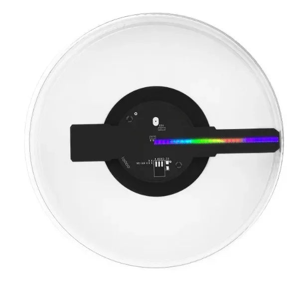
E-Ink Display Technology
The calendar features a 7.5-inch, 800x480 resolution e-ink display, optimized for low power consumption and extended readability. It uses a grayscale technique to improve visuals, perfect for battery-powered, long-term use. -
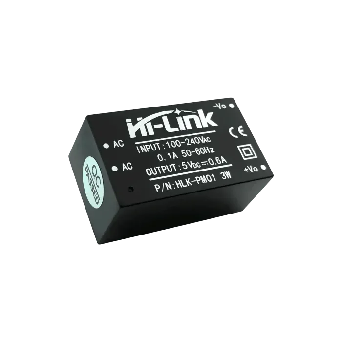
ESP32 Platform Integration
Built on the powerful ESP32 microcontroller, ChronoPortal offers dual-core processing, Wi-Fi, and Bluetooth functionality. It connects to the internet to sync real-time and weather data, utilizing OpenWeatherMap for dynamic weather updates. -
Open-Source and Customizable
All source code and 3D-printable case files are available on GitHub, enabling users to modify the project to fit their needs and contribute to its development.
Core Features
-
Date and Time Display: Shows the current date and time, including year, month, day, hour, minute, and second.
-
Weather Information: Integrates with OpenWeatherMap to provide either a 5-day or 12-hour forecast, displaying average weather conditions, high/low temperatures, and humidity.
-
Reminders and Notifications: Users can set reminders for important events, meetings, or birthdays to stay organized.
-
Customizable Themes: Users can switch themes to personalize the calendar according to their style and preferences.
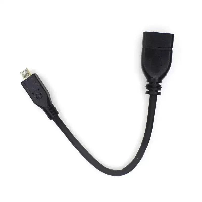
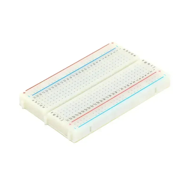
Components
Assembly Instructions for ChronoPortal
Before starting, it’s important to know that this project involves soldering and trimming the included display wiring harness. As the display is the most expensive component, it’s highly recommended to test the display first before cutting any wires to ensure it works properly. If defective, you’ll still have the option to return it. You can temporarily solder the pin headers to connect the harness directly. After testing, desolder them and proceed with the assembly steps below.

-
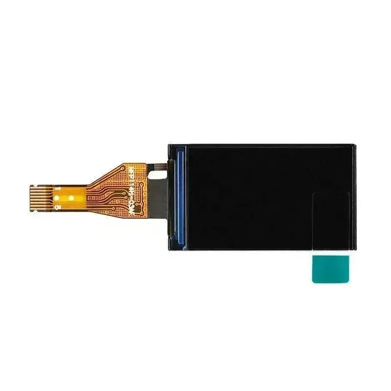
Prepare the E-Ink Display:
-
If the display has a protective film, remove it by pulling the colored tab in the corner.
-
Gently pre-bend the ribbon cable and insert the display into the front.stl part, aligning the cable with the side slot.
⚠️ Caution: The ribbon cable and display are fragile, so handle them carefully to avoid damage.

-
Assemble the Case:
-
Ensure the display sits flush with the top and bottom edges of the front cover.
-
Place the back.stl component over the display, making sure the ribbon cable slides smoothly into the side slot.
-
Use M3x8 screws to secure the back cover to the front at each corner.

Connecting the E-Paper Driver HAT and ESP32
-
Connect the Driver Board:
-
Insert the e-Paper Driver HAT into the slot near the ribbon cable. Clip the ribbon cable into the connector and latch it securely.
-
Ensure the Display Config switch is set to B and the Interface Config switch to 0 to ensure proper functionality.
-
Wire the ESP32 to the Driver HAT:
Below is the wiring chart. Note that the PWR pin exists only on Waveshare driver board versions 2.3 or later.
If you have an older revision, ignore the PWR connection:
| e-Paper HAT | <-> | ESP32 |
| VCC (Grey) | <-> | 3.3v |
| GND (Brown) | <-> | GND |
| DIN (Blue) | <-> | IO13 |
| CLK (Yellow) | <-> | IO14 |
| CS (Orange) | <-> | IO15 |
| DC (Green) | <-> | IO23 |
| RST (White) | <-> | IO33 |
| BUSY (Purple) | <-> | IO27 |
| PWR (Red) | <-> | IO32 |
Final Assembly
-
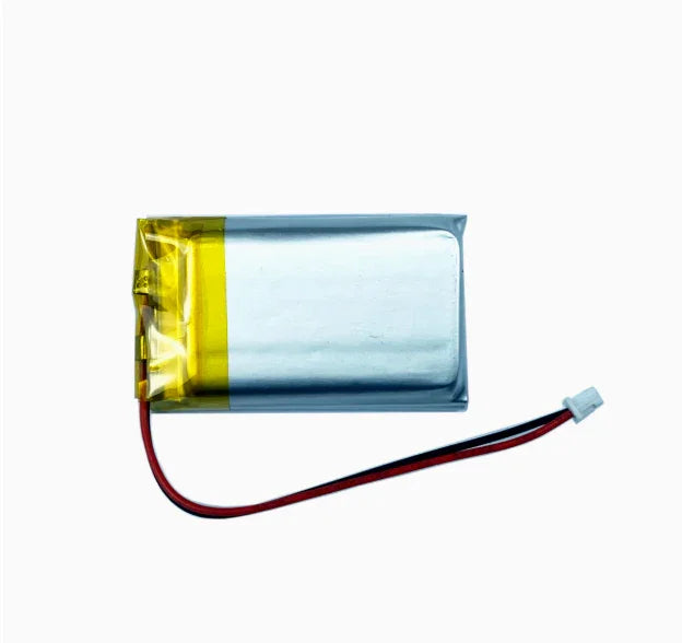
Attach the Battery Holder:
-
Use plastic bonder (e.g., JB Weld) to secure the battery holder inside the case.
-
Solder the red and black battery wires to the Vin and GND pins on the ESP32 board.

-
Secure the Cover:
-
Tuck all wires inside the case recess to prevent pinching. Ensure the ESP32 sits firmly in its place.
-
Install the printed cover.stl and secure it with M3x8 screws in each corner and one at the center above the battery holder.

Programming ESP32
Do not insert the batteries yet, as the ESP32 still needs to be programmed. Once the firmware is uploaded and tested, the batteries can be installed to power the device.
This streamlined process ensures your display works correctly before final assembly and that all components are safely secured for long-term operation.
more infomation: https://github.com/wuspy/portal_calendar?tab=readme-ov-file