


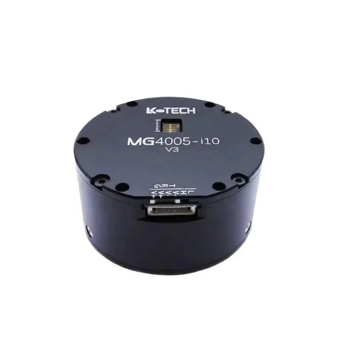


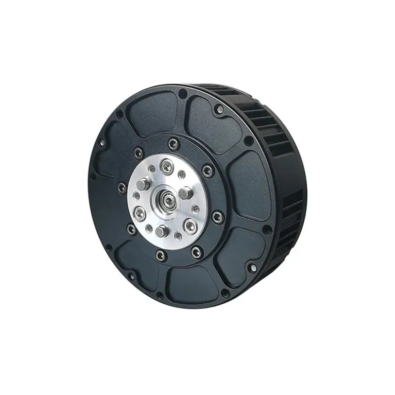
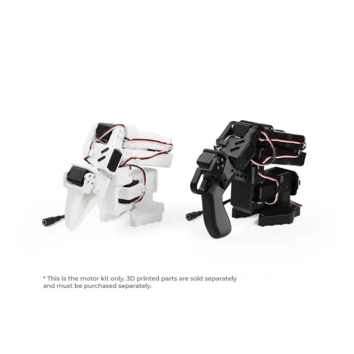


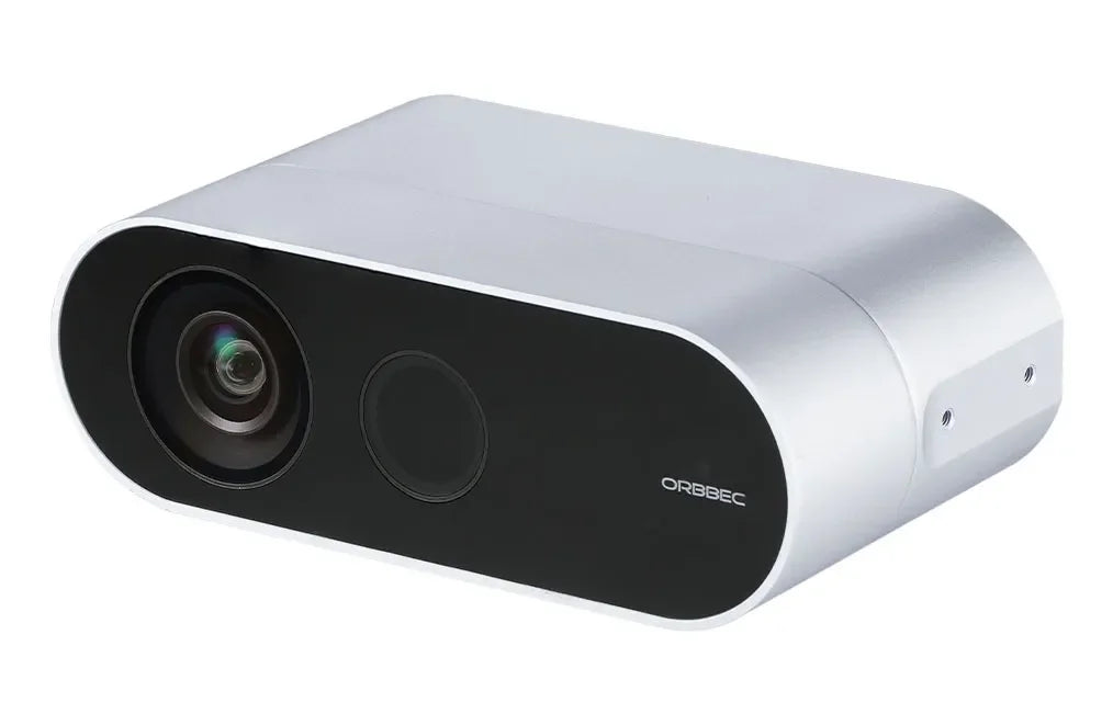


What is XiaoMi CyberGear Micromotor
The Xiaomi CyberGear Micromotor is a compact yet powerful micromotor designed for advanced robotic and bionic applications. It features a high torque-to-size ratio, fast response times and precise control, enabling realistic and fluid movements in robotic limbs and mechanisms. Its modular design and intelligent control algorithms facilitate seamless integration into complex systems, making it suitable for applications ranging from bionic prosthetics to advanced robotic pets. Xiaomi emphasises its potential to create more lifelike and interactive robotic experiences.
CyberGear Micromotor Instruction Manual
Precautions
-
Please use it according to the working parameters specified in this article, otherwise it will cause serious damage to this product!
-
The control mode cannot be switched while the joint is running. If you need to switch, you need to send a stop command before switching.
-
Please check whether all parts are intact before use. If parts are missing or damaged, please contact technical support in time.
-
Do not disassemble the motor at will to avoid irrecoverable faults.
-
Make sure there is no short circuit when connecting the motor and the interface is connected correctly as required.
Legal Notices
Before using this product, the user must read this manual carefully and operate the product in accordance with the contents of this manual. If the user uses this product in violation of the contents of this manual, the company does not assume any responsibility for any property damage or personal injury accidents. Since this product consists of many parts, do not let children come into contact with this product to avoid accidents. In order to extend the service life of the product, please do not use this product in high temperature and high pressure environments. This manual has tried its best to include various function introductions and usage instructions at the time of printing. However, due to the continuous improvement of product functions, design changes, etc., there may still be discrepancies with the products purchased by users.
There may be differences between this manual and the actual product in terms of color, appearance, etc. Please refer to the actual product. This manual is published by Xiaomi or its local subsidiaries. Xiaomi may make necessary improvements and changes to this manual for typographical errors, inaccuracies of the latest information, or improvements to programs and/or equipment at any time without prior notice. Such changes will be uploaded to the new version of this manual. Please scan the QR code of this manual to obtain it. All pictures are for functional description only. Please refer to the actual product.
After-sales policy
The after-sales service of this product is strictly in accordance with the "Consumer Rights and Interests Protection Law of the People's Republic of China" and the "Product Quality Law of the People's Republic of China". The service content is as follows:
Warranty period and content
Users who place an order to purchase this product through online channels can enjoy a no-reason return service within seven days from the day of receipt. When returning goods, users must present a valid proof of purchase and return the invoice. Users must ensure that the returned goods maintain their original quality and functionality, their appearance is intact, and the trademarks and logos of the goods themselves and accessories are complete. If there are any gifts, they must be returned together. If the product is damaged artificially, dismantled manually, the packaging box is missing, or the spare parts are missing, returns will not be processed. The logistics costs incurred when returning goods shall be borne by the user (see "After-sales Service Charging Standards" for charging standards). If the user fails to settle the logistics fees, the actual amount will be deducted from the refund amount. The paid price will be returned to the user within seven days from the date of receipt of the returned goods. Refund methods are the same as payment methods. The specific arrival date may be affected by factors such as banks and payment institutions.
If non-human-damaged performance failure occurs within 7 days from the day after the user signs for it, the Xiaomi after-sales service center will handle the return business for the user after inspection and confirmation. When returning the product, the user must present a valid purchase certificate and return the invoice. Any gifts must be returned together.
If non-human damage or performance failure occurs within 7 days to 15 days from the day after the user signs for it, Xiaomi after-sales service center will handle the exchange business for the user and replace the entire set of products after inspection and confirmation. After the exchange, the three-guarantee period of the product itself will be recalculated.
From 15 days to 365 days from the day after the user signs for it, after inspection and confirmation by the Xiaomi after-sales service center, it is a quality failure of the product itself, and repair services can be provided free of charge. The replaced faulty product belongs to Xiaomi Company. Non-faulty product will be returned in its original condition. This product leaves the factory after undergoing various strict tests. If there is any quality failure that is not related to the product itself, we will have the right to refuse the user's return or exchange request.
If the after-sales policy in this manual is inconsistent with the store’s after-sales policy, the store’s after-sales policy shall prevail.
Non-warranty regulations: The following situations are not covered by the warranty:
Exceeds the warranty period limited by the warranty terms.
Product damage caused by incorrect use without following the instructions.
Damage caused by improper operation, maintenance, installation, modification, testing and other improper use.
Conventional mechanical loss and wear caused by non-quality faults.
Damage caused by abnormal working conditions, including but not limited to falling, impact, liquid immersion, violent impact, etc.
Damage caused by natural disasters (such as floods, fires, lightning strikes, earthquakes, etc.) or force majeure.
Damage caused by use beyond peak torque.
Items that are not genuine Xiaomi products may not be able to provide legal proof of purchase.
Other failures or damages not caused by problems such as product design, technology, manufacturing, quality, etc.
Use this product for commercial purposes.
If the above situation occurs, users need to pay the fees themselves. For details of the group’s after-sales policy, please see: https://www.mi.com/service/serviceAgreement?id=17
Motor specifications
1.1 Appearance and installation dimensions
1.2 Standard usage status
1.2.1 Rated voltage: 24 VDC
1.2.2 Operating voltage range: 16V—28 VDC
1.2.3 Rated load (CW): 4 N.m
1.2.4 Running direction: CW/CCW viewed from the direction of the shaft
1.2.5 Usage posture: The axis direction is horizontal or vertical
1.2.6 Standard operating temperature: 25±5°C
1.2.7 Operating temperature range: -20 ~ 50°C
1.2.8 Standard operating humidity: 65%
1.2.9 Operating humidity range: 5 ~ 85%, no condensation
1.2.10 Storage temperature range: -30 ~ 70°C
1.2.11 Insulation level: Class B
1.3 Electrical characteristics
1.3.1 No-load speed: 296 rpm±10%
1.3.2 No-load current: 0.5 Arms
1.3.3 Rated load: 4 N.m
1.3.4 Rated load speed: 240rpm±10% 1.3.5 Rated load current (peak): 6.5A±10% 1.3.6 Peak load: 12 N.m
1.3.7 Peak current (peak value): 23A±10%
1.3.8 Insulation resistance/stator winding: DC 500VAC, 100M Ohms 1.3.9 High voltage resistance/stator and casing: 600 VAC, 1s, 2mA 1.3.10 Motor back electromotive force: 0.054-0.057Vrms/rpm
1.3.11 Line resistance: 0.45Ω±10%
1.3.12 Torque constant: 0.87N.m/Arms
1.3.13 Motor inductance: 187-339μH
1.3.14 T-N curve
1.3.15 Maximum overload curve Test conditions:
Ambient temperature: 25°C
Winding limit temperature: 120°C
Speed:24rpm
Maximum load curve
Maximum overload time (s) vs Torque(N.m)
Test Data
| Load | Operating time (s) |
| 12 | 28 |
| 11 | 45 |
| 10 | 60 |
| 9 | 90 |
| 8 | 160 |
| 7 | 320 |
| 6 | 700 |
| 5 | 1800 |
| 4.5 | 2500 |
| 4 | rated |
1.4 Mechanical properties
1.4.1 Weight: 317g±3g
1.4.2 Number of poles: 28 poles 1.4.3 Number of phases: 3 phases
1.4.4 Drive mode: FOC
1.4.5 Reduction ratio: 7.75:1
Drive product information
2.1 Driver appearance introduction & product specifications
24V power supply and CAN communication integrated terminal;
Hardware version and laser engraving QR code;
MCU download port;
CAN communication test point;
Indicator light;
Installation holes; 7. “C, A, B” are the three-phase winding welding points;
Product specifications
| Rated operating voltage | 24VDC |
| Maximum allowed voltage | 28VDC |
| Rated operating current | 6.5A |
| Maximum allowed current | 23A |
| Standby power consumption | ≤18mA |
| CAN bus bit rate | 1Mbps |
| Size | Φ58mm |
| Working environment temperature | -20°C 50°C |
| Maximum temperature allowed by the control board | 80°C |
| Encoder resolution | 14bit (single lap absolute value) |
2.2 Driver interface definition
2.2.1 Driver interface diagram
2.2.2 Recommended brands and models of drive interfaces
| # | Board model | Brand manufacturer | Line end model | Brand manufacturer |
| 1 | XT30PB(2+2)-M.G.B | AMASS (AMS) | XT30(2+2)-F.G.B | AMASS (AMS) |
| 2 | 2.0mm-2P female | / | 2.0mm-2P male | / |
| 3 | 2.54mm-4P female | / | 2.54mm-4P male | / |
2.2.3 Driver interface pin definition
Power supply and CAN communication port
CAN communication test pad
Download port
| # | Interface function | PIN | Description |
| 1 | Power and CAN communication | 1 | Power supply positive (+) |
| 2 | Negative pole of power supply (-) | ||
| 3 | CAN communication low side CAN_L | ||
| 4 | CAN communication high side CAN_H | ||
| 2 | CAN communication test point | 1 | CAN communication low side CAN_L |
| 2 | CAN communication high side CAN_H | ||
| 3 | Download port | 1 | SWDIO(data) |
| 2 | SWCLK(clock) | ||
| 3 | 3V3 (positive 3.3V) | ||
| 4 | GND (negative ground) |
2.3 Definition of driver indicator light
Blue signal light and red power indicator light
Indicator light definition
| Power indicator light (red light when on) | The power indicator light is used to indicate the MCU 3.3V power supply. When the total power input is 24V, the light turns red, which proves that the entire network is powered normally. If the power supply is 24V, the indicator light does not light up and the power needs to be cut off immediately |
| Signal indicator light (blue light when on) | When the signal light flashes, it proves that the MCU is running normally and the driver chip is running normally |
2.4 Main components and specifications
| # | Component type | Model | Quantity |
| 1 | MCU chip | GD32F303RET6 | 1 PCS |
| 2 | Driver chip | 6EDL7141 | 1 PCS |
| 3 | Magnetic encoder chip | AS5047P | 1 PCS |
| 4 | Thermistor | NXFT15XH103FEAB021/NCP18XH103F03RB | 2 PCS |
| 5 | Power MOS | JMGG031V06A | 6 PCS |
Debugger usage instructions (scan the QR code at the end of the paper manual to obtain the debugger)
3.1 Hardware configuration
The joint motor uses CAN communication. There are two communication lines, which are connected to the debugger through a can-to-USB tool. The debugger needs to install the ch340 driver in advance and works in AT mode by default.
It should be noted that we developed the debugger based on a specific can to USB tool, so we need to use our recommended serial port tool for debugging. If you want to port it to other debugger platforms, you can refer to Chapter 3 of the manual. development.
The can to USB tool recommends using YourCee's USB-CAN module. The frame header corresponding to the serial port protocol is 41 54 and the frame tail is 0D 0A.
3.2 Debugger interface and description
mainly include:
A. Module selection
-
Device module
-
Configuration module
-
Analysis module
-
Help module
B. Submodule selection Equipment modules include
-
Connect or disconnect electrical equipment
-
Motor equipment information
-
Motor encoder calibration
-
Modify motor CAN ID
-
Set the mechanical zero position of the motor
-
Motor program upgrade
Configuration modules include:
-
Parameter table, you can view and modify motor parameters
-
Upload parameters. You can upload the parameters in the motor to the parameter table
-
Download parameters. You can download the data from the parameter table to the motor
-
Export parameters. You can download the data from the parameter table to the local
-
Factory reset, you can restore the data in the parameter table to factory settings.
-
Clear warning, you can clear motor errors, such as excessive temperature, etc.
Analysis modules include:
-
Oscilloscope to view parameter changes over time
-
Frequency, you can adjust the frequency of viewing data
-
Channel, you can configure the data to be viewed
-
Start and stop drawing
-
Output waveform data to local
Help modules include:
-
Instructions for use, you can open the instruction manual
-
About, you can view software information
C. Motor information query
-
Device Information
-
Parameter table information
D. Data column
-
Log information
-
Communication information
E. Run the debugging area
-
Select device
-
Convenient operation area, you can quickly control the forward and reverse rotation of the motor
-
Motion control area, which can control the motor to operate in various modes
F. Submodule display area
3.3 Motor settings
3.3.1 Motor connection settings
Connect the can to USB tool (install ch340 driver, work in AT mode by default), select the device module, click the connection submodule, and select the corresponding serial port connection.
3.3.2 Basic settings
Modify the motor ID number.
-
Motor magnetic braiding calibration, reinstalling the motor board and motor, or reconnecting the motor wires in a different order, etc. require re-magnetic braiding calibration.
-
Set the zero position (lost in case of power failure) and set the current position to 0.
-
Motor program upgrade. When the motor program is updated, click the upgrade button to select the upgrade file to upgrade.
3.3.3 Parameter list
After successfully connecting the motor, click the parameter table module in the configuration module, and all parameters will be displayed in the log. The loading is successful, indicating that the relevant parameters of the motor have been successfully read (Note: the parameter table needs to be in the standby state of the motor. Configure in the state, if the motor is in the running state, the parameter table cannot be refreshed) The interface will display the electrical Relevant parameters of the motor. The blue parameters are the internal storage parameters of the motor. They can be found directly after the corresponding parameters. Modify the previous value column. Click Download Parameters to download the parameters in the debugger to the motor. Click Upload. Parameters can upload the parameters in the motor to the debugger. The green parameters of the motor are observed parameters, which are The collected parameters can be observed in real time.
Note: Please do not change the motor's torque limit, protection temperature, and over-temperature time at will. Due to illegal operation of this book If the product causes harm to the human body or irreversible damage to joints, our company will not be held liable for any legal consequences. legal responsibility.
Parameters Table
| Function code | Name | Parameter Type | Attributes | Maximum value | Minimum value | Current value (for reference) | Remark |
| 0x0000 | Name | String | read/write | ÿÿÿÿÿÿÿÿÿÿÿÿÿÿÿÿ | |||
| 0x0001 | BarCode | String | read/write | ÿÿÿÿÿÿÿÿÿÿÿÿÿÿÿÿ | |||
| 0x1000 | BootCodeVersion | String | read only | 0.1.5 | |||
| 0x1001 | BootBuildDate | String | read only | Mar 16 2022 | |||
| 0x1002 | BootBuildTime | String | read only | 20:22:09 | |||
| 0x1003 | AppCodeVersion | String | read only | 0.1.5 | Motor program version number | ||
| 0x1004 | AppGitVersion | String | read only | 7b844b0fM | |||
| 0x1005 | AppBuildDate | String | read only | Apr 14 2022 | |||
| 0x1006 | AppBuildTime | String | read only | 20:30:22 | |||
| 0x1007 | AppCodeName | String | read only | dog_motor | |||
| 0x2000 | echoPara1 | uint16 | Configuration | 74 | 5 | 5 | |
| 0x2001 | echoPara2 | uint16 | Configuration | 74 | 5 | 5 | |
| 0x2002 | echoPara3 | uint16 | Configuration | 74 | 5 | 5 | |
| 0x2003 | echoPara4 | uint16 | Configuration | 74 | 5 | 5 | |
| 0x2004 | echoFreHz | uint32 | read/write | 10000 | 1 | 500 | |
| 0x2005 | MechOffset | float | set up | 7 | -7 | 4.619583 | Motor magnetic encoder angle offset |
| 0x2006 | MechPos_init | float | read/write | 50 | -50 | 4.52 | Reference angle during initial multi-turn |
| 0x2007 | limit_torque | float | read/write | 12 | 0 | 12 | Torque limit |
| 0x2008 | I_FW_MAX | float | read/write | 33 | 0 | 0 | Field weakening current value, default 0 |
| 0x2009 | motor_index | uint8 | set up | 20 | 0 | 1 | Motor index, marks the motor joint position |
| 0X200a | CAN_ID | uint8 | set up | 127 | 0 | 1 | This node id |
| 0x200b | CAN_MASTER | uint8 | set up | 127 | 0 | 0 | can host id |
| 0x200c | CAN_TIMEOUT | uint32 | read/write | 100000 | 0 | 0 | can timeout threshold, default 0 |
| 0x200d | motorOverTemp | int16 | read/write | 1500 | 0 | 800 | Motor protection temperature value, temp (degree) *10 |
| 0x200e | overTempTime | uint32 | read/write | 1000000 | 1000 | 20000 | Overtemperature time |
| 0x200f | GearRatio | float | read/write | 64 | 1 | 7.75 | Transmission ratio |
| 0x2010 | Tq_caliType | uint8 | read/write | 1 | 0 | 1 | Torque calibration method setting |
| 0x2011 | cur_filt_gain | float | read/write | 1 | 0 | 0.9 | Current filter parameters |
| 0x2012 | cur_kp | float | read/write | 200 | 0 | 0.025 | Current kp |
| 0x2013 | cur_ki | float | read/write | 200 | 0 | 0.0258 | electric current ki |
| 0x2014 | spd_kp | float | read/write | 200 | 0 | 2 | Speed kp |
| 0x2015 | spd_ki | float | read/write | 200 | 0 | 0.021 | speed ki |
| 0x2016 | loc_kp | float | read/write | 200 | 0 | 30 | Location kp |
| 0x2017 | spd_filt_gain | float | read/write | 1 | 0 | 0.1 | Speed filter parameters |
| 0x2018 | limit_spd | float | read/write | 200 | 0 | 2 | Position mode speed limit |
| 0x2019 | limit_cur | float | read/write | 23 | 0 | 23 | Position, speed mode current limit |
| 0x3000 | timeUse0 | uint16 | read only (computing) | 5 | |||
| 0x3001 | timeUse1 | uint16 | read only (computing) | 0 | |||
| 0x3002 | timeUse2 | uint16 | read only (computing) | 10 | |||
| 0x3003 | timeUse3 | uint16 | read only (computing) | 0 | |||
| 0x3004 | encoderRaw | uint16 | read only (computing) | 11396 | Magnetic Encoder Sample Value | ||
| 0x3005 | mcuTemp | int16 | read only (computing) | 337 | mcu internal temperature *10 | ||
| 0x3006 | motorTemp | int16 | read only (computing) | 333 | motor ntc temperature *10 | ||
| 0x3007 | vBus(mv) | uint16 | read only (computing) | 24195 | busbar voltage | ||
| 0x3008 | adc1Offset | int32 | read only (computing) | 2084 | adc Sampling Channel 1 Zero current bias | ||
| 0x3009 | adc2Offset | int32 | read only (computing) | 2084 | adc sample channel 2 zero current bias | ||
| 0x300a | adc1Raw | uint16 | read only (computing) | 1232 | adc Sampling value 1 | ||
| 0x300b | adc2Raw | uint16 | read only (computing) | 1212 | adc Sampling value 2 | ||
| 0x300c | VBUS | float | read only (computing) | 24.195 | Busbar voltage V | ||
| 0x300d | cmdId | float | read only (computing) | 0 | id ring command, A | ||
| 0x300e | cmdIq | float | read only (computing) | 0 | iq ring command, A | ||
| 0x300f | cmdlocref | float | read only (computing) | 0 | Position loop command, rad | ||
| 0x3010 | cmdspdref | float | read only (computing) | 0 | Velocity loop command, rad/s | ||
| 0x3011 | cmdTorque | float | read only (computing) | 0 | Torque command, nm | ||
| 0x3012 | cmdPos | float | read only (computing) | 0 | mit Protocol Angle Command | ||
| 0x3013 | cmdVel | float | read only (computing) | 0 | mit protocol speed indicator virtuous | ||
| 0x3014 | rotation | int16 | read only (computing) | 1 | number of laps | ||
| 0x3015 | modPos | float | read only (computing) | 4.363409 | Motor uncalculated mechanical angle, rad | ||
| 0x3016 | mechPos | float | read only (computing) | 0.777679 | Load-side Loop Counting Machinery Angle, rad | ||
| 0x3017 | mechVel | float | read only (computing) | 0.036618 | load-side steering Speed, rad/s | ||
| 0x3018 | elecPos | float | read only (computing) | 4.714761 | Electrical angle | ||
| 0x3019 | ia | float | read only (computing) | 0 | U line current, A | ||
| 0x301a | ib | float | read only (computing) | 0 | V line current, A | ||
| 0x301b | ic | float | read only (computing) | 0 | W line current, A | ||
| 0x301c | tick | uint32 | read only (computing) | 31600 | |||
| 0x301d | phaseOrder | uint8 | read only (computing) | 0 | Calibration direction markers | ||
| 0x301e | iqf | float | read only (computing) | 0 | iq Filter value, A | ||
| 0x301f | boardTemp | int16 | read only (computing) | 359 | Temperature on board, *10 | ||
| 0x3020 | iq | float | read only (computing) | 0 | iq original value, A | ||
| 0x3021 | id | float | read only (computing) | 0 | id Original value, A | ||
| 0x3022 | faultSta | uint32 | read only (computing) | 0 | Fault status value | ||
| 0X3023 | warnSta | uint32 | read only (computing) | 0 | Warning status value | ||
| 0x3024 | drv_fault | uint16 | read only (computing) | 0 | Driver Chip Fault Value | ||
| 0x3025 | drv_temp | int16 | read only (computing) | 48 | Driver Chip Temperature value, degree | ||
| 0x3026 | Uq | float | read only (computing) | 0 | q Axis voltage | ||
| 0x3027 | Ud | float | read only (computing) | 0 | d Axis voltage | ||
| 0x3028 | dtc_u | float | read only (computing) | 0 | U-phase output duty cycle | ||
| 0x3029 | dtc_v | float | read only (computing) | 0 | V Phase Output Duty Cycle | ||
| 0x302a | dtc_w | float | read only (computing) | 0 | W Phase Output Duty Cycle | ||
| 0x302b | v_bus | float | read only (computing) | 24.195 | vbus in closed loop | ||
| 0x302c | v_ref | float | read only (computing) | 0 | Closed-loop vq,vd synthesis input voltage | ||
| 0x302d | torque_fdb | float | read only (computing) | 0 | Torque feedback value, nm | ||
| 0x302e | rated_i | float | read only (computing) | 8 | Motor rated current | ||
| 0x302f | limit_i | float | read only (computing) | 27 | Motor maximum current limit |
3.3.4 Oscilloscope
This interface supports viewing and observing the graph generated by real-time data. The observable data includes motor Id/Iq current, temperature, output real-time speed, rotor (encoder) position, output position, etc.
Click the oscilloscope module in the analysis module, select the appropriate parameters in the channel (for parameter meanings, please refer to 3.3.3), set the output frequency and click Start Drawing to observe the data spectrum, stop drawing to stop observing the spectrum.
3.4 Control demo
jog run:
Set the maximum speed, click Run, and then click JOG to run the motor in forward and reverse directions
Control mode switching:
The motor control mode can be converted to the motion mode interface.
3.4.1 Zero point mode
Click the switch button on the right, and the motor will slowly return to the mechanical zero position.
3.4.2 Operation control mode
Click the switch button on the right, then set the five parameter values, click Start or Continuous Send, the motor will return to the feedback frame and run according to the target instruction; click the switch button on the right again and the motor will stop.
3.4.2 Current mode
Manually switch the current mode, click the switch button on the right, and then set the Iq current command value, start or send continuously, the motor will follow the current command, click the switch button on the right again, the motor will stop.
Click the switch button on the right side of the control mode, enter the amplitude and frequency of the sinusoidal automatic test, and then click Click the switch button on the right side of the sine automatic test, and the motor's iq (A) will run according to the set amplitude and frequency.
3.4.3 Speed mode
Manually switch to speed mode, click the switch button on the right, and then set the speed command value (-30~30rad/s), start or send continuously, the motor will follow the speed command, click the switch button on the right again, the motor will stop.
3.4.4 Location mode
Manually switch the position mode, click the switch button on the right, then set the position command value (rad), start or send continuously, the motor will follow the target position command, click the switch button on the right again, the motor will stop. You can modify the maximum speed of position following by setting the speed.
Click the switch button on the right side of the control mode, enter the amplitude and frequency of the sine-based automatic test, and then click the switch button on the right side of the sine-based automatic test. The motor position (rad) will run according to the set amplitude and frequency.
3.5 Firmware update
The first step is to click the upgrade of the device module and select the bin file to be burned; the second step is to confirm the upgrade and the motor will start to update the firmware. After the progress is completed, the motor update will be completed and it will restart automatically.
Driver communication protocol and usage instructions
Motor communication is CAN 2.0 communication interface, with a baud rate of 1Mbps and an extended frame format, as shown
| Data field | 29-bit ID | 8 Byte data area | ||
| Size | Bit 28 ~ 24 | Bit 23 ~ 8 | Bit 7 ~ 0 | Byte 0 ~ 7 |
| Description | Communication type | Data area 2 | Target address | Data area 1 |
The control modes supported by the motor include:
-
Operation control mode: given 5 parameters for motor operation control;
-
Current mode: given the specified Iq current of the motor;
-
Speed mode: given the specified operating speed of the motor;
-
Position mode: Given a specified position of the motor, the motor will run to the specified position;
4.1 Communication protocol type description
4.1.1 Get device ID (communication type 0); Get the device's ID and 64-bit MCU unique identifier
Request frame:
| Data field | 29-bit ID | 8 byte data area | ||
| Position | Bit 28 ~ 24 | Bit 23 ~ 8 | Bit 7 ~ 0 | Byte 0 ~ 7 |
| Description | 0 | Bit 15 ~ 8: Host CAN_ID | Motor CAN_ID | 0 |
Response frame:
| Data field | 29-bit ID | 8 byte data area | ||
| Position | Bit 28 ~ 24 | Bit 23 ~ 8 | Bit 7 ~ 0 | Byte 0 ~ 7 |
| Description | 0 | Motor CAN_ID | 0xFE | 64-bit MCU unique identifier |
4.1.2 Motor control instructions (communication type 1) in operation control mode are used to send control instructions to the motor.
Request frame:
| Data field | 29-bit ID | 8 byte data area | ||
| Position | Bit 28 ~ 24 | Bit 23 ~ 8 | Bit 7 ~ 0 | Byte 0 ~ 7 |
| Description | 1 | Byte 2: Torque (0 ~ 65535) corresponding to (- 12Nm ~ 12Nm) | Motor CAN_ID | Byte 0 ~ 1: Target angle [0 ~ 65535] corresponding to (-4π ~ 4π) Byte 2 ~ 3: Target angular velocity [0 ~ 65535] corresponds to (- 30rad/s ~ 30rad/s) Byte 4 ~ 5: Kp [0 ~ 65535] corresponds to (0.0 ~ 500.0) Byte 6 ~ 7: Kd [0 ~ 65535] corresponds to (0.0 ~ 5.0) |
Response frame: Reply motor feedback frame (see communication type 2)
4.1.3 Motor feedback data (communication type 2) is used to feedback the motor operating status to the host
| Data field | 29-bit ID | 8 byte data area | ||
| Position | Bit 28 ~ 24 | Bit 23 ~ 8 | Bit 7 ~ 0 | Byte 0 ~ 7 |
| Description | 2 | Bit 8 ~ 15: Motor CAN ID Bit 21 ~ 16: Fault information (0 - No, 1 - Yes) Bit 21: not calibrated Bit 20: HALL encoding failure Bit 19: Magnetic encoding failure Bit 18: over temperature Bit 17: overcurrent Bit 16: Undervoltage fault Bit 22 ~ 23: mode status: 0: Reset mode [reset] 1: Cali mode [Calibration] 2: Motor mode [Run] |
Host CAN_ID | Byte 0 ~ 1: Current angle [0 ~ 65535] corresponds to (-4π ~ 4π) Byte 2 ~ 3: Current angular velocity [0 ~ 65535] corresponds to (-30rad/s ~ 30rad/s) Byte 4 ~ 5: Current torque [0 ~ 65535] corresponds to (-12Nm ~ 12Nm) Byte 6 ~ 7: Current temperature: Temp (degrees Celsius) )*10 |
4.1.4 Motor enable operation (communication type 3)
| Data field | 29-bit ID | 8 byte data area | ||
| Position | Bit 28 ~ 24 | Bit 23 ~ 8 | Bit 7 ~ 0 | Byte 0 ~ 7 |
| Description | 3 | Bit 15 ~ 8: Host CAN_ID | Motor CAN_ID |
Reply frame: Reply motor feedback frame (see communication type 2)
4.1.5 Motor stopped (communication type 4)
| Data field | 29-bit ID | 8 byte data area | ||
| Position | Bit 28 ~ 24 | Bit 23 ~ 8 | Bit 7 ~ 0 | Byte 0 ~ 7 |
| Description | 4 | Bit 15 ~ 8: Host CAN_ID | Motor CAN_ID | During normal operation, the data area needs to be cleared to 0; When Byte[0]=1: Clear fault; |
Reply frame: Reply motor feedback frame (see communication type 2)
4.1.6 Setting the mechanical zero position of the motor (communication type 6) will set the current motor position to the mechanical zero position (lost after power failure)
| Data field | 29-bit ID | 8 byte data area | ||
| Position | Bit 28 ~ 24 | Bit 23 ~ 8 | Bit 7 ~ 0 | Byte 0 ~ 7 |
| Description | 6 | Bit 15 ~ 8: Host CAN_ID | Motor CAN_ID | Byte[0]=1 |
Reply frame: Reply motor feedback frame (see communication type 2)
4.1.7 Set motor CAN_ID (communication type 7) to change the current motor CAN_ID, which will take effect immediately.
| Data field | 29-bit ID | 8 byte data area | ||
| Position | Bit 28 ~ 24 | Bit 23 ~ 8 | Bit 7 ~ 0 | Byte 0 ~ 7 |
| Description | 7 | Bit 15 ~ 8: Host CAN_ID Bit 16 ~ 23: New motor CAN_ID |
Motor CAN_ID | Byte[0]=1 |
Reply frame: Reply motor broadcast frame (see communication type 0)
4.1.8 Single parameter reading (communication type 17)
| Data field | 29-bit ID | 8 byte data area | ||
| Position | Bit 28 ~ 24 | Bit 23 ~ 8 | Bit 7 ~ 0 | Byte 0 ~ 7 |
| Description | 17 | Bit 15 ~ 8: Host CAN_ID | Motor CAN_ID | Byte 0 ~ 1: index, see 4.1.11 for parameter list Byte 2 ~ 3: 00 Byte 4 ~ 7: 00 |
Response frame:
| Data field | 29-bit ID | 8 byte data area | ||
| Position | Bit 28 ~ 24 | Bit 23 ~ 8 | Bit 7 ~ 0 | Byte 0 ~ 7 |
| Description | 17 | Bit 15 ~ 8: Motor CAN_ID | Host CAN_ID | Byte 0 ~ 1: index, for parameter list, see 4.1.11 Byte 2 ~ 3: 00 Byte 4 ~ 7: parameter data, 1 byte data is in Byte 4 |
4.1.9 Single parameter writing (communication type 18) (lost after power failure)
| Data field | 29-bit ID | 8 byte data area | ||
| Position | Bit 28 ~ 24 | Bit 23 ~ 8 | Bit 7 ~ 0 | Byte 0 ~ 7 |
| Description | 18 | Bit 15 ~ 8: Host CAN_ID | Motor CAN_ID | Byte 0 ~ 1: index, see 4.1.11 for parameter list details Byte 2 ~ 3: 00 Byte 4 ~ 7: parameter data |
Reply frame: Reply motor feedback frame (see communication type 2)
4.1.10 Fault feedback frame (communication type 21)
| Data field | 29-bit ID | 8 byte data area | ||
| Position | Bit 28 ~ 24 | Bit 23 ~ 8 | Bit 7 ~ 0 | Byte 0 ~ 7 |
| Description | 21 | Bit 15 ~ 8: Host CAN_ID | Motor CAN_ID | Byte 0 ~ 3: fault value (not 0: fault, 0: normal) Bit 16: A phase current sampling overcurrent Bit 15 ~ 8: overload fault Bit 7: encoder not calibrated Bit 5: C phase current sampling overcurrent Bit 4: B phase current sampling overcurrent bit3: overvoltage fault Bit 2: under-voltage fault bit1: driver chip fault bit0: motor over-temperature fault, default 80 degrees Byte 4 ~ 7: warning value Bit 0: motor over-temperature warning, default 75 degrees |
4.1.11 Baud rate modification (communication type 22) (version 1.2.1.5 can be modified, please refer to the document process to modify it carefully. Operation errors may cause problems such as being unable to connect to the motor and being unable to upgrade)
| Data field | 29-bit ID | 8 byte data area | ||
| Position | Bit 28 ~ 24 | Bit 23 ~ 8 | Bit 7 ~ 0 | Byte 0 ~ 7 |
| Description | 22 | Bit 15 ~ 8: Host CAN_ID | Motor CAN_ID | Byte0: Motor baud rate 1: 1Mbps 2: 500kbps 3: 250kbps 4: 125kbps |
Reply frame: Reply motor broadcast frame (see communication type 0)
4.1.12 Readable and writable single parameter list (7019-7020 is readable by firmware version 1.2.1.5)
| Parameter index | parameter name | describe | type | Number of bytes | Possible values | Permission |
| 0x7005 | run_mode | 0: Operation control mode 1: Position mode 2: Speed mode 3: Current mode |
uint8 | 1 | W/R | |
| 0x7006 | iq_ref | Current Mode Iq Command | float | 4 | -23 ~ 23A | W/R |
| 0x700A | spd_ref | Speed mode speed command | float | 4 | -30 ~ 30rad/s | W/R |
| 0x700B | limit_torque | Torque limit | float | 4 | 0~12Nm | W/R |
| 0x7010 | cur_kp | Kp of current | float | 4 | Default value 0.125 | W/R |
| 0x7011 | cur_ki | Current Ki | float | 4 | Default value 0.0158 | W/R |
| 0x7014 | cur_filt_gain | Current filter coefficient filt_gain | float | 4 | 0~1.0, default value W/R 0.1 | W/R |
| 0x7016 | loc_ref | Position mode angle command | float | 4 | rad | W/R |
| 0x7017 | limit_spd | Position mode speed limit | float | 4 | 0 ~ 30rad/s | W/R |
| 0x7018 | limit_cur | Speed Position Mode Current Limit | float | 4 | 0 ~ 23A | W/R |
| 0x7019 | mechPos | Load end lap counting mechanical angle | float | 4 | rad | R |
| 0x701A | iqf | iq filter value | float | 4 | -23 ~ 23A | R |
| 0x701B | mechVel | Load end speed | float | 4 | -30 ~ 30rad/s | R |
| 0x701C | VBUS | bus voltage | float | 4 | V | R |
| 0x701D | rotation | Number of turns | int16 | 2 | Number of turns | W/R |
| 0x701E | loc_kp | kp of position | float | 4 | Default value 30 | W/R |
| 0x701F | spd_kp | Speed in kp | float | 4 | Default value 1 | W/R |
| 0x7020 | spd_ki | Speed of ki | float | 4 | Default value 0.002 | W/R |
4.2 Instructions for use of control mode
4.2.1 Program sample
The following provides examples of controlling motors in various modes (taking gd32f303 as an example). The following is called libraries, functions and macro definitions for various examples.
#define P_MIN -12.5f
#define P_MAX 12.5f
#define V_MIN -30.0f
#define V_MAX 30.0f
#define KP_MIN 0.0f
#define KP_MAX 500.0f
#define KD_MIN 0.0f
#define KD_MAX 5.0f
#define T_MIN -12.0f
#define T_MAX 12.0f

struct exCanIdInfo{
    uint32_t id:8;
    uint32_t data:16;
    uint32_t mode:5;
    uint32_t res:3;
};

can_receive_message_struct rxMsg;

can_trasnmit_message_struct txMsg = {
    .tx_sfid = 0,
    .tx_efid = 0xff,
    .tx_ft = CAN_FT_DATA,
    .tx_ff = CAN_FF_EXTENDED,
    .tx_dlen = 8,
};

#define txCanIdEx (((struct exCanIdInfo)&(txMsg.tx_efid)))

// Parse extended frame id into custom data structure
#define rxCanIdEx (((struct exCanIdInfo)&(rxMsg.rx_efid)))

int float_to_uint(float x, float x_min, float x_max, int bits) {
    float span = x_max - x_min;
    float offset = x_min;
    if(x > x_max) x=x_max;
    else if(x < x_min) x= x_min;
    return (int) ((x-offset)*((float)((1<
✔ Copied!
Operation control mode motor control instructions (communication type 1)
void motor_controlmode(uint8_t id, float torque, float MechPosition, float speed, float kp, float kd) {
    txCanIdEx.mode = 1;
    txCanIdEx.id = id;
    txCanIdEx.res = 0;
    txCanIdEx.data = float_to_uint(torque,T_MIN,T_MAX,16);
    txMsg.tx_dlen = 8;
    txMsg.tx_data[0]=float_to_uint(MechPosition,P_MIN,P_MAX,16)>>8;
    txMsg.tx_data[1]=float_to_uint(MechPosition,P_MIN,P_MAX,16);
    txMsg.tx_data[2]=float_to_uint(speed,V_MIN,V_MAX,16)>>8;
    txMsg.tx_data[3]=float_to_uint(speed,V_MIN,V_MAX,16);
    txMsg.tx_data[4]=float_to_uint(kp,KP_MIN,KP_MAX,16)>>8;
    txMsg.tx_data[5]=float_to_uint(kp,KP_MIN,KP_MAX,16);
    txMsg.tx_data[6]=float_to_uint(kd,KD_MIN,KD_MAX,16)>>8;
    txMsg.tx_data[7]=float_to_uint(kd,KD_MIN,KD_MAX,16);
    can_txd();
}
✔ Copied!
Motor stop running frame (communication type 4)
void motor_reset(uint8_t id, uint16_t master_id) {
    txCanIdEx.mode = 4;
    txCanIdEx.id = id;
    txCanIdEx.res = 0;
    txCanIdEx.data = master_id;
    txMsg.tx_dlen = 8;
    for(uint8_t i=0;i<8;i++) {
        txMsg.tx_data[i]=0;
    }
    can_txd();
}
✔ Copied!
Motor mode parameter write command (communication type 18, operating mode switching)
uint8_t runmode;
uint16_t index;
void motor_modechange(uint8_t id, uint16_t master_id) {
    txCanIdEx.mode = 0x12;
    txCanIdEx.id = id;
    txCanIdEx.res = 0;
    txCanIdEx.data = master_id;
    txMsg.tx_dlen = 8;
    for(uint8_t i=0;i<8;i++) {
        txMsg.tx_data[i]=0;
    }
    memcpy(&txMsg.tx_data[0],&index,2);
    memcpy(&txMsg.tx_data[4],&runmode, 1);
    can_txd();
}
✔ Copied!
Motor mode parameter write command (communication type 18, control parameter write)
uint16_t index;
float ref;
void motor_write(uint8_t id, uint16_t master_id) {
    txCanIdEx.mode = 0x12;
    txCanIdEx.id = id;
    txCanIdEx.res = 0;
    txCanIdEx.data = master_id;
    txMsg.tx_dlen = 8;
    for(uint8_t i=0;i<8;i++) {
        txMsg.tx_data[i]=0;
    }
    memcpy(&txMsg.tx_data[0],&index,2);
    memcpy(&txMsg.tx_data[4],&ref,4);
    can_txd();
}
✔ Copied!
4.2.2 Operation control mode
After the motor is powered on, it is in the operation control mode by default;
Send motor enable running frame (communication type 3) -->
Send operation control mode motor control command (communication type 1) -->
Receive motor feedback frame (communication type 2)
4.2.3 Current mode
Send the motor mode parameter write command (communication type 18) and set the runmode parameter to 3 --->
Send the motor enable run frame (communication type 3) -->
Send the motor mode parameter write command (communication type 18) and set the iq_ref parameter is the preset current command
4.2.4 Speed mode
Send the motor mode parameter write command (communication type 18) and set the runmode parameter to 2 --->
Send the motor enable run frame (communication type 3) -->
Send the motor mode parameter write command (communication type 18) and set the limit_cur parameter For the preset maximum current command -->
Send motor mode parameter write command (communication type 18) to set the spd_ref parameter to the preset speed command
4.2.5 Location mode
Send the motor mode parameter write command (communication type 18) and set the runmode parameter to 1 -->
Send the motor enable run frame (communication type 3) -->
Send the motor mode parameter write command (communication type 18) and set the limit_spd parameter to Preset maximum speed command -->
Send motor mode parameter write command (communication type 18) to set the loc_ref parameter to the preset position command
4.2.6 Stop operation
Send motor stop frame (communication type 4)
CyberGear library for M5 stack
https://github.com/project-sternbergia/cybergear_m5/tree/main
cybergear_m5
M5 stack library for cybergear
"Remember, with great torque comes great responsibility."
Supported framework
-
Arduino for ESP32
Supported device (ESP32)
-
M5Stack Basic V2.7
H/W Components (MCP2515)
H/W Components (ESP32 + PWRCAN)
H/W Components (ESP32 + CAN Transceiver Unit)
How to use Official GUI tool
This software requires a specific CAN to USB module. The official documentation recommends YourCee's USB to CAN module, which supports the serial protocol with a frame header of 41 54 and frame tail of 0D 0A, but this is not readily available, so we searched Aliexpress for an alternative. ※ Note that this will not work for general modules.
Tested(for reference):
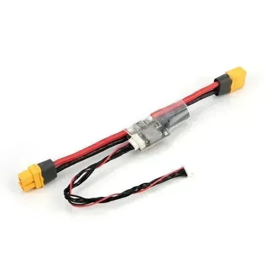
Recommended pre-crimped cables
-
XT30(2+2) Cable
How to run sample
Arduino IDE
-
cd ~/Arduino/libraries
-
git clone https://github.com/coryjfowler/MCP_CAN_lib.git
-
git clone https://github.com/Locoduino/RingBuffer.git
-
git clone git@github.com:project-sternbergia/arduino-CAN.git
-
git clone https://github.com/project-sternbergia/cybergear_m5.git
-
Open cybergear_m5/examples/control_mode_example.ino with Arduino IDE
-
Put this file in the same folder as control_mode_example.ino (for Arduino IDE) If you want to use ESP32_CAN library, please commentin this lines.
-
Build and write firmware to M5Stack
Sample Code
control_mode_example.ino
Check cybergear behaviour using M5 stack.
-
Middle Button - Change Control Mode (Position Mode -> Speed Mode -> Current Mode)
-
Right Button - Increase control value
-
Left Button - Decrease control value
cybergear_bilateral.ino
This example use two cybergears for leader and follower. Before you test this example, please change cybergear can id as follows. After that write cybergear_m5/examples/cybergear_bilateral.ino to m5 stack throughout Arduino IDE.
-
leader cybergear : 0x7F
-
follower cybergear : 0x7E
Recommended Articles