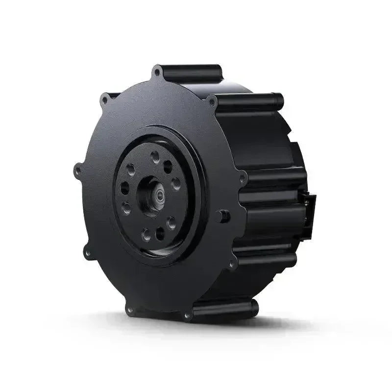
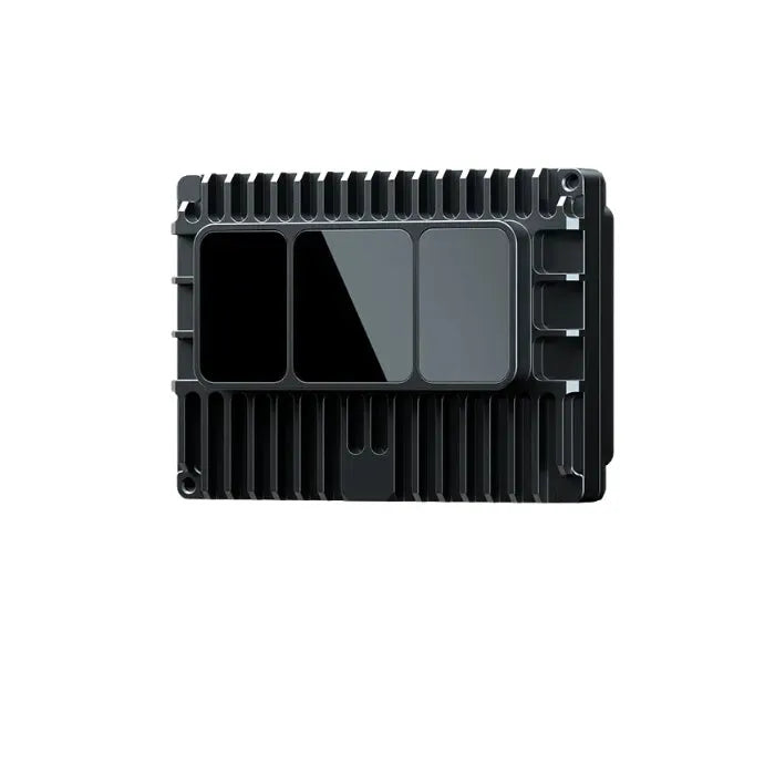
Appearance Overview & Product Specifications of Xiaomi CyberGear Motor Driver
Integrated 24V Power Supply and CAN Communication Terminals
-
24V DC Power Supply: The driver supports a standard 24V DC power supply, ensuring stable operation in various working environments.
-
CAN Communication Interface: The integrated CAN (Controller Area Network) interface enables efficient communication with other electronic systems, ensuring higher system integration and faster response times.
Hardware Version and Laser-Engraved QR Code
-
Laser-Engraved QR Code: The QR code on the driver housing ensures product uniqueness, allowing for quick traceability and management, which simplifies after-sales service and quality control.
-
Hardware Version Identification: Clearly marked hardware versions enable technicians to quickly identify models for system upgrades, compatibility checks, and maintenance.
MCU Download Port
The driver is equipped with a dedicated MCU (Microcontroller Unit) download port for firmware updates and system debugging. Technicians can use this port to quickly upload new firmware, optimize system performance, or conduct real-time troubleshooting.
CAN Communication Test Points
For assembly and maintenance convenience, the driver features dedicated CAN communication test points. Technicians can verify the integrity and functionality of communication lines, significantly improving debugging efficiency and fault resolution.
Indicator Light Design
Multiple indicator lights are provided to display the operational status of the driver and system:
-
Power Indicator: Displays whether the device is receiving power normally.
-
Signal Indicator: Reflects communication status and signal transmission, assisting in monitoring and identifying potential issues.
Standardized Mounting Holes
The driver housing is designed with standardized mounting holes to ensure secure installation onto compatible vehicles or equipment. This design improves installation efficiency and enhances operational reliability.
Three-Phase Winding Terminals (C, A, B)
-
Efficient Connection: Standardized welding points ensure a secure and efficient connection between the motor windings and the driver.
-
Stable Power Transmission: Optimized collaboration between the motor and driver improves operational reliability and overall efficiency.
| Item Specification | |
| Rated Operating Voltage | 24VDC |
| Maximum Allowed Voltage | 28VDC |
| Rated Operating Current | 6.5A |
| Maximum Allowed Current | 23A |
| Standby Power Consumption | ≤18mA |
| CAN Bus Bit Rate | 1Mbps |
| Dimensions | Φ58mm |
| Operating Environment Temperature | -20°C to 50°C |
| Maximum Allowable Temperature for Control Board | 80°C |
| Encoder Resolution | 14bit (Single Turn Absolute) |
Drive Interface Definitions
Drive Interface Diagram

Drive Interface Recommended Models
| Serial No. | Board Side Model | Wire Side Model |
| 1 | XT30PB(2+2)-M.G.B | XT30(2+2)-F.G.B |
| 2 | 2.0mm-2P Solder Pad | 2.0mm-2P Probe |
| 3 | 2.54mm-4P Solder Pad | 2.54mm-4P Probe |
Driver Interface Pin Definitions
Power supply and CAN communication port:


| Serial No. | Interface Function | Pin No. | Description |
| 1 | Power and CAN Interface | 1 | Power Positive (+) |
| 2 | Power Negative (-) | ||
| 3 | CAN Low (CAN_L) | ||
| 4 | CAN High (CAN_H) | ||
| 2 | CAN Communication Test Points | 1 | CAN Low (CAN_L) |
| 2 | CAN High (CAN_H) | ||
| 3 | Download Port | 1 | SWDIO (Data) |
| 2 | SWCLK (Clock) | ||
| 3 | 3V3 (Positive 3.3V) | ||
| 4 | GND (Ground) |
Drive Indicator Definition

| Indicator Light Definition | Description |
| Power Indicator Light (Red) | The power indicator light is used to show the MCU’s 3.3V power status. When the total input voltage is 24V, the light will be red, indicating that the network is operating properly. If the input power is below 24V, the indicator will need to be powered off. |
| Signal Indicator Light (Blue) | The signal indicator light flashes when the MCU is operating normally and the chip is functioning correctly. |
Main components and specifications
| Serial No. | Item | Part Number | Quantity |
| 1 | MCU Chip | GD32F303RET6 | 1 piece |
| 2 | Driver Chip | 6EDL7141 | 1 piece |
| 3 | Magnetic Encoder Chip | AS5047P | 1 piece |
| 4 | Sensitive Resistor | NXFT15XH103FEAB021/NCP18XH103F03RB | 2 pieces |
| 5 | Power MOSFET | JMGG031V06A | 6 pieces |
-
MCU Chip: The microcontroller unit (MCU) acts as the ’brain’ of the device, responsible for controlling and coordinating other components.
-
Driver Chip: This component drives motors or other actuators by converting control signals into drive signals.
-
Magnetic Encoder Chip: Used to detect the motor's speed and position, providing essential feedback for precise control.
-
Thermistor: Monitors the temperature of the device, ensuring safe operation and preventing overheating.
-
Power MOSFET: A power semiconductor device commonly used in motor drive circuits to efficiently switch and control high-power signals.
Driver communication protocol and instructions for use
The motor communication is a CAN 2.0 communication interface with a baud rate of 1 Mbps and an extended frame format as shown below:
|
Data Domain |
29-bit ID |
8-Byte Data Field |
||
|
Dimension |
Bit28~bit24 |
bit23~8 |
bit7~0 |
Byte0~Byte7 |
|
Description |
Type of communication |
Data area 2 |
target addresses |
Data area 1 |
The motor supports the following control modes:
-
Comprehensive Control Mode: Set five operational control parameters for the motor to achieve integrated control.
-
Current Mode: Specify the target Iq current to achieve precise current regulation.
-
Speed Mode: Specify a target running speed for the motor to maintain.
-
Position Mode: Specify a target position, and the motor will move to and hold that position.
Main components and specifications
| Serial No. | Item | Part Number | Quantity |
| 1 | MCU Chip | GD32F303RET6 | 1 piece |
| 2 | Driver Chip | 6EDL7141 | 1 piece |
| 3 | Magnetic Encoder Chip | AS5047P | 1 piece |
| 4 | Sensitive Resistor | NXFT15XH103FEAB021/NCP18XH103F03RB | 2 pieces |
| 5 | Power MOSFET | JMGG031V06A | 6 pieces |
-
MCU Chip: The microcontroller unit (MCU) acts as the "brain" of the device, responsible for controlling and coordinating other components.
-
Driver Chip: This component drives motors or other actuators by converting control signals into drive signals.
-
Magnetic Encoder Chip: Used to detect the motor's speed and position, providing essential feedback for precise control.
-
Thermistor: Monitors the temperature of the device, ensuring safe operation and preventing overheating.
-
Power MOSFET: A power semiconductor device commonly used in motor drive circuits to efficiently switch and control high-power signals.
Driver communication protocol and instructions for use
The motor communication is a CAN 2.0 communication interface with a baud rate of 1 Mbps and an extended frame format as shown below:
| Data Domain | 29-bit ID | 8-Byte Data Field | ||
| Dimension | Bit28~bit24 | bit23~8 | bit7~0 | Byte0~Byte7 |
| Description | Type of communication | Data area 2 | target addresses | Data area 1 |
The motor supports the following control modes:
-
Comprehensive Control Mode: Set five operational control parameters for the motor to achieve integrated control.
-
Current Mode: Specify the target Iq current to achieve precise current regulation.
-
Speed Mode: Specify a target running speed for the motor to maintain.
-
Position Mode: Specify a target position, and the motor will move to and hold that position.
Communication protocol type description
-
get device ID (communication type 0); get device ID and 664-bit MCU unique identifier
| Data Domain | 29-bit ID | 8-Byte Data Field | ||
| Dimension | Bit28~bit24 | bit23~8 | bit7~0 | Byte0~Byte7 |
| Description | 0 | bit15~8: used to identify the host CAN_ID |
Target motor CAN_ID | 0 |
| Data Domain | 29-bit ID | 8-Byte Data Field | ||
| Dimension | Bit28~bit24 | bit23~8 | bit7~0 | Byte0~Byte7 |
| Description | 0 | Target motor CAN_ID | 0XFE | 64-bit MCU unique identifier |
-
Operation mode motor control commands (communication type 1) are used to send control commands to the motor.
| Data Domain | 29-bit ID | 8-Byte Data Field | ||
| Dimension | Bit28~bit24 | bit23~8 | bit7~0 | Byte0~Byte7 |
| Description | 1 | Byte2: Torque (0~65535) corresponding to (-12Nm12Nm) |
Target motor CAN _ID | Byte0~1:Target angle[0~65535] corresponds to(-4π~4π) Byte2~3:Target angular velocity[0~65535] corresponds to(-30rad/s~30rad/s) Byte4~5:Kp[0~65535] corresponds to(0.0~500.0) Byte6~7:Kd [0~65535] corresponds to (0.0~5.0) |
-
Motor feedback data (communication type 2) is Used to provide feedback to the host computer on the motor operating status.
| Data Domain | 29-bit ID | 8-Byte Data Field | ||
| Dimension | Bit28~bit24 | bit23~8 | bit7~0 | Byte0~Byte7 |
| Description | 2 | Bit8~Bit15: Current motor CAN ID bit21~16: Fault message (0 no 1 yes) bit21: Not calibrated bit20: HALL code fault bit19: Magnetic encoding fault bit18: Over temperature bit17: Overcurrent bit16: Undervoltage fault bit22~23: Mode Status 0 : Reset mode [Reset] 1: Cali mode [Calibration] 2: Motor mode [Run] |
Host CAN_ID | Byte0~1:Target angle[0~65535] corresponds to(-4π~4π) Byte2~3:Target angular velocity[0~65535] corresponds to(-30rad/s~30rad/s) Byte4~5:Kp[0~65535] corresponds to(0.0~500.0) Byte6~7:Kd [0~65535] corresponds to (0.0~5.0)Byte0~1:Current angle[0~65535] corresponds to(-4π~4π) Byte2~3:Current angular velocity[0~65535] corresponds to(-30rad/s~30rad/s) Byte4~5:Current torque[0~65535] corresponds to(-12Nm~12Nm) Byte6~7:Current temperature:Temp(Celsius)*10 |
-
Motor enable operation (communication type 3)
| Data Domain | 29-bit ID | 8-Byte Data Field | ||
| Dimension | Bit28~bit24 | bit23~8 | bit7~0 | Byte0~Byte7 |
| Description | 4 | bit15~8: used to identify the main CAN_ID |
Target motor CAN_ID | During normal operation, the data area should be cleared 0; Byte[0]=1: clear fault; |
Answer frame: Answer motor feedback frame (see communication type 2)
-
Motor stop (communication type 4)
| Data Domain | 29-bit ID | 8-Byte Data Field | ||
| Dimension | Bit28~bit24 | bit23~8 | bit7~0 | Byte0~Byte7 |
| Description | 4 | bit15~8: used to identify the main CAN_ID |
Target motor CAN_ID | During normal operation, the data area should be cleared 0; Byte[0]=1: clear fault; |
Answer frame: Answer motor feedback frame (see communication type 2)
-
Setting the motor mechanical zero position (communication type 6) sets the current motor position to the mechanical zero position (lost at power down)
| Data Domain | 29-bit ID | 8-Byte Data Field | ||
| Dimension | Bit28~bit24 | bit23~8 | bit7~0 | Byte0~Byte7 |
| Description | 6 | bit15~8: used to identify the main CAN_ID | Target motor CAN_ID | Byte[0]=1 |
Answer frame: Answer motor feedback frame (see communication type 2)
-
Setting the motor CAN_ID (communication type 7) Changing the current motor CAN_ID takes effect immediately.
| Data Domain | 29-bit ID | 8-Byte Data Field | ||
| Dimension | Bit28~bit24 | bit23~8 | bit7~0 | Byte0~Byte7 |
| Description | 7 | Bit15~8: Used to identify the main CAN_ID. Bit16~23: Pre-set CAN_ID |
Target motor CAN_ID | |
Answer frame: Answer motor feedback frame (see communication type 0)
-
Individual parameter reading (communication type 17)
| Data Domain | 29-bit ID | 8-Byte Data Field | ||
| Dimension | Bit28~bit24 | bit23~8 | bit7~0 | Byte0~Byte7 |
| Description | 17 | bit15~8: used to identify the main CAN_ID | Target motor CAN_ID | Byte0~1: index, parameter columns See communication type 22 for details. Byte2~3: 00 Byte4~7: 00 |
| Data Domain | 29-bit ID | 8-Byte Data Field | ||
| Dimension | Bit28~bit24 | bit23~8 | bit7~0 | Byte0~Byte7 |
| Description | 17 | bit15~8: used to identify the main CAN_ID | Target motor CAN_ID | Byte0~1: index, see communication type 22 for parameter list. Byte2~3: 00 Byte4~7: parameter data, 1 byte data in Byte4 |
-
Individual parameter writes (communication type 18) (power-down loss)
| Data Domain | 29-bit ID | 8-Byte Data Field | ||
| Dimension | Bit28~bit24 | bit23~8 | bit7~0 | Byte0~Byte7 |
| Description | 18 | bit15~8: used to identify the main CAN_ID | Target motor CAN_ID | Byte0~1: index, parameter list details See communication type 22 Byte2~3: 00 Byte4~7: parameter data |
Answer frame: Answer motor feedback frame (see communication type 2)
-
Fault feedback frames (communication type 21)
| Data Domain | 29-bit ID | 8-Byte Data Field | ||
| Dimension | Bit28~bit24 | bit23~8 | bit7~0 | Byte0~Byte7 |
| Description | 21 |
bit15~8: used to identify the main CAN_ID |
Motor CAN_ID | Byte0~3: fault value (not 0: faulty, 0: normal) bit16:A phase current sampling overcurrent bit15~bit8:overload fault bit7:Encoder not calibrated bit5:C phase current sampling overcurrent bit4:B phase current sampling overcurrent bit3:Overvoltage fault bit2:Undervoltage fault bit1:Driver chip fault bit0:Motor over temperature fault, default 80 degrees. Byte4~7: warning value Byte4~7: warning value bit0: motor over-temperature warning, default 75 degrees |
-
Baud rate modification (communication type 22) (please refer to the documented procedure and modify it carefully, as the incorrect operation will result in problems such as failure to connect the motor and failure to upgrade)
| Data Domain | 29-bit ID | 8-Byte Data Field | ||
| Dimension | Bit28~bit24 | bit23~8 | bit7~0 | Byte0~Byte7 |
| Description | 22 |
bit15~8: used to identify the main CAN_ID |
Target motor CAN_ID | Byte0: Motor baud rate 1: 1Mbps 2: 500kbps 3: 250kbps 4:125kbps |
Answer frame: Answer motor broadcast frame (see communication type 0)
-
Individual parameter lists can be read and written (7019-7020 are firmware version 1.2.1.5 readable).
| Parameters index |
Parameter name |
Description | Type | Bytes | Unit/Description | R/W read/write permissions |
| 0X7005 | run_mode | 0: Operational Control Mode 1: Position mode 2: Velocity Mode 3: Current Mode |
uint8 | 1 | W/R | |
| 0X7006 | iq_ref | Current Mode Iq Command |
float | 4 | -23~23A | W/R |
| 0X700A | spd_ref | RPM Mode RPM Command |
float | 4 | -30~30rad/s | W/R |
| 0X700B | imit_torque | Torque Limit | float | 4 | 0~12Nm | W/R |
| 0X7010 | cur_kp | Kp of current | float | 4 | Default value 0.125 | W/R |
| 0X7011 | cur_ki | Ki of the current | float | 4 | Default value 0.0158 | W/R |
| 0X7014 | cur_filt_gain | Current filter coefficient filt_gain |
float | 4 | 0~1.0, default value 0.1 | W/R |
| 0X7016 | loc_ref | Position Mode Angle Command |
float | 4 | rad | W/R |
| 0X7017 | limit_spd | Position Mode Speed Limit |
float | 4 | 0~30rad/s | W/R |
| 0X7018 | limit_cur | Velocity Position Mode Current Limit |
float | 4 | 0~23A | W/R |
| 0x7019 | mechPos | Load End Gauge Mechanical Angle |
float | 4 | rad | R |
| 0x701A | iqf | Iq Filter value | float | 4 | -23~23A | R |
| 0x701B | mechVel | Load-side speed | float | 4 | -30~30rad/s | R |
| 0x701C | VBUS | busbar voltage | float | 4 | V | R |
| 0x701D | rotation | number of laps | int16 | 2 | number of laps | W/R |
| 0x701E | loc_kp | kp of position | float | 4 | Default value 30 | W/R |
| 0x701F | spd_kp | kp of speed | float | 4 | Default value 1 | W/R |
| 0x7020 | spd_ki | ki of the velocity | float | 4 | Default value 0.002 | W/R |
FAQs
Q1: What is the maximum temperature the Xiaomi cybergear motor control board can reach?
A1: Under normal operating conditions, the maximum working temperature of the Xiaomi CyberGear motor control board is typically around 80°C. However, during peak loads or high-performance operation, critical components such as MOSFETs and power regulators may briefly reach temperatures of 100°C to 120°C (212°F to 248°F).
To ensure reliable operation and prevent thermal damage, it is recommended to implement appropriate cooling solutions, such as heat sinks, cooling fans, or proper ventilation, to effectively manage temperatures and extend the device's lifespan.
Featured Articles
More Information
 openelab.de
 openelab.com


