openelab.de
 openelab.com














































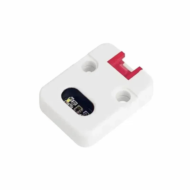
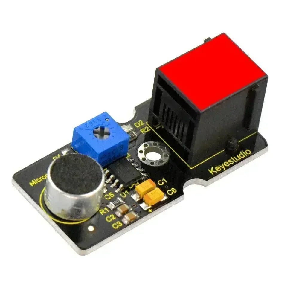
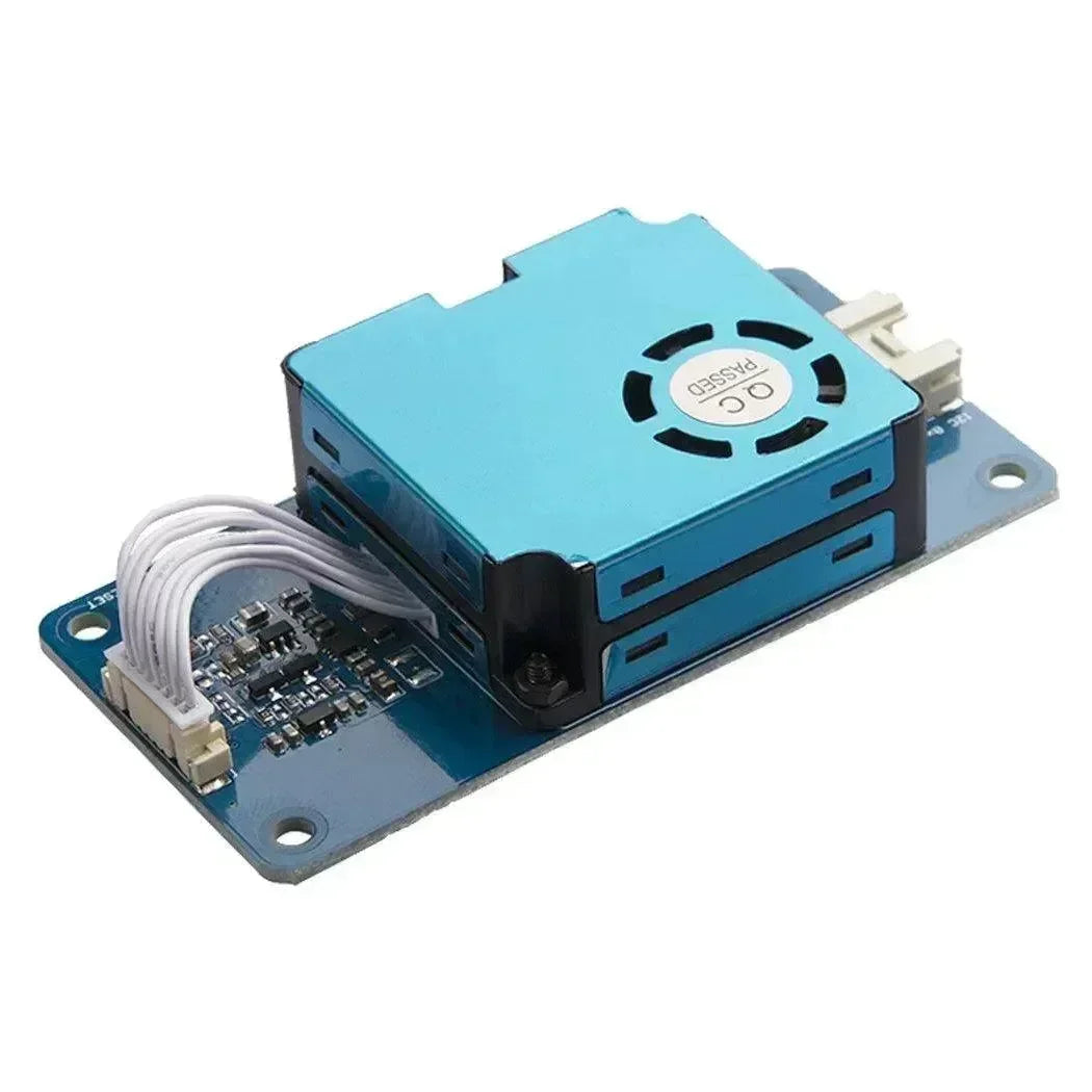

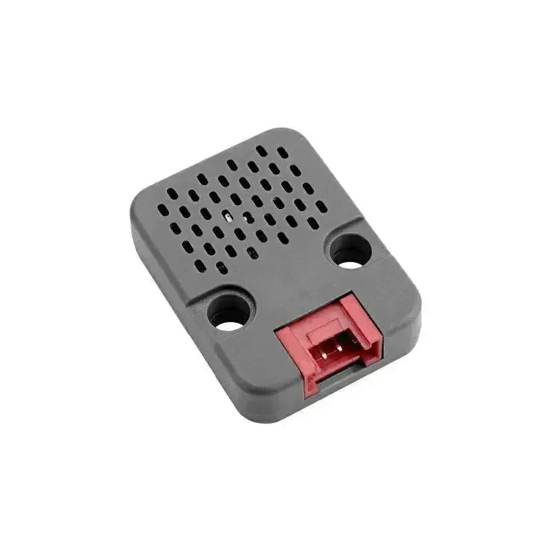








The Remote Hardware Module enables reading, writing, and monitoring of GPIO pins on a remote node. Configuration option: Enabled.
Note: For firmware versions above 2.5.3, this module requires compiling your own firmware and removing the -DMESHTASTIC_EXCLUDE_REMOTEHARDWARE=1 build flag from platformio.ini. While configuration options for this module may appear in clients, GPIO setting and reading are currently supported only through the Meshtastic Python CLI.
Remote Hardware Config Parameters
Ensure the module is enabled.
Remote Hardware Module Availability in Clients
Android
All configuration options for the Remote Hardware Module are available in the Android app. Open the Meshtastic App and go to Settings > Remote Hardware.
Apple
All configuration options for the Remote Hardware Module are available in the iOS, iPadOS, and macOS apps (version and higher) under Settings > Module Configuration > Remote Hardware.
CLI
All Remote Hardware Module configuration settings can be managed via the Python CLI.
Web
Not implemented.
Remote Hardware Module Operation
Tip: Accessing GPIO pins carries inherent risks, as incorrect settings can damage or destroy your hardware. Make sure you fully understand the schematic of your specific device before proceeding, as no warranty is provided. Use this feature at your own risk.
Supported Operations
You can set any GPIO, read any GPIO, and receive mesh notifications whenever a GPIO changes state. Note that rapid transitions—such as button presses—cannot be detected; for those use cases, refer to the Detection Sensor module. The results of GPIO reads, as well as notifications of GPIO state changes, are also published over MQTT (if enabled) in JSON format (if enabled).
Setup
You can install the latest Python tools and libraries by running pip3 install --upgrade meshtastic on Windows, Linux, or OS‑X. Refer to the Python section for additional details.
To prevent unauthorized access, you must first create a GPIO channel that provides authenticated access to this feature. This channel must be added to both the local and remote nodes, and the module must be enabled on both devices.
The steps using the Python command‑line tool are as follows:
-
Connect the local device via USB
-
Enable the Remote Hardware module
| meshtastic --set remote_hardware.enabled true |
-
Create a GPIO channel:
| meshtastic --ch-add gpio |
-
Verify the channel has been created, then copy the long “Complete URL” that includes all channels on the device.
| meshtastic --info |
-
Connect the remote device via USB, or access it through the mesh using the remote admin feature.
-
Enable the Remote Hardware module on the remote device.
| meshtastic --set remote_hardware.enabled true |
-
Configure the remote device to join the GPIO channel you previously created.
| meshtastic --seturl theurlyoucopiedinstep3 |
Both devices should now be able to communicate through the GPIO channel. To confirm, send a text message from one device to the other. You can also run --nodes to ensure the second node is detected.
Masks
A mask is used to specify which GPIOs to control. For GPIO 1, bit 1 of the mask is set (hexadecimal 0x2); for GPIO 2, bit 2 of the mask is set (0x4); and so forth. To determine the correct mask for the pin(s) you want to use, the Python program (and its output) shown below may be helpful.
| >>> for i in range(1,45): ... print(f'GPIO:{i} mask:{hex(2**i)}') ... GPIO:1 mask:0x2 GPIO:2 mask:0x4 GPIO:3 mask:0x8 GPIO:4 mask:0x10 GPIO:5 mask:0x20 GPIO:6 mask:0x40 GPIO:7 mask:0x80 GPIO:8 mask:0x100 GPIO:9 mask:0x200 GPIO:10 mask:0x400 GPIO:11 mask:0x800 GPIO:12 mask:0x1000 GPIO:13 mask:0x2000 GPIO:14 mask:0x4000 GPIO:15 mask:0x8000 GPIO:16 mask:0x10000 GPIO:17 mask:0x20000 GPIO:18 mask:0x40000 GPIO:19 mask:0x80000 GPIO:20 mask:0x100000 GPIO:21 mask:0x200000 GPIO:22 mask:0x400000 GPIO:23 mask:0x800000 GPIO:24 mask:0x1000000 GPIO:25 mask:0x2000000 GPIO:26 mask:0x4000000 GPIO:27 mask:0x8000000 GPIO:28 mask:0x10000000 GPIO:29 mask:0x20000000 GPIO:30 mask:0x40000000 GPIO:31 mask:0x80000000 GPIO:32 mask:0x100000000 GPIO:33 mask:0x200000000 GPIO:34 mask:0x400000000 GPIO:35 mask:0x800000000 GPIO:36 mask:0x1000000000 GPIO:37 mask:0x2000000000 GPIO:38 mask:0x4000000000 GPIO:39 mask:0x8000000000 GPIO:40 mask:0x10000000000 GPIO:41 mask:0x20000000000 GPIO:42 mask:0x40000000000 GPIO:43 mask:0x80000000000 GPIO:44 mask:0x100000000000 |
Managing GPIOs through the Python CLI
Note: You can control or monitor the GPIOs of your USB‑connected node by setting --dest to the local node’s ID. In this case, no GPIO channel is required.
Writing a GPIO
Example: turning 'on' GPIO4
|
meshtastic --port /dev/ttyUSB0 --gpio-wrb 4 1 --dest 28979058 |
Reading a GPIO
Example: read GPIO4
| meshtastic --port /dev/ttyUSB0 --gpio-rd 0x10 --dest 28979058 # Connected to radio # Reading GPIO mask 0x10 from !28979058 # GPIO read response gpio_value=16 |
Note: If the mask and the gpio_value match, then the value is "on". If the gpio_value is 0, then the value is "off".
Watching for GPIO Changes
Example: watching GPIO4 for changes
| meshtastic --port /dev/ttyUSB0 --gpio-watch 0x10 --dest 28979058 # Connected to radio # Watching GPIO mask 0x10 from !28979058 # Received RemoteHardware typ=GPIOS_CHANGED, gpio_value=16 # Received RemoteHardware typ=GPIOS_CHANGED, gpio_value=0 # Received RemoteHardware typ=GPIOS_CHANGED, gpio_value=16 # < press ctrl-c to exit > |
GPIO Operation Testing
You can perform GPIO operations directly from your own Python code by using the Meshtastic RemoteHardwareClient class. For further details, refer to the Python API documentation.
To confirm that the GPIO operations function correctly, you can connect a simple LED and resistor as a test. Use the provided tutorial as a reference guide.
Requirements
-
2× Meshtastic devices (one connected to a local computer, the other simply powered and used for the LED connection)
-
2× wires (commonly black for ground and yellow for signal, though any colors may be used)
-
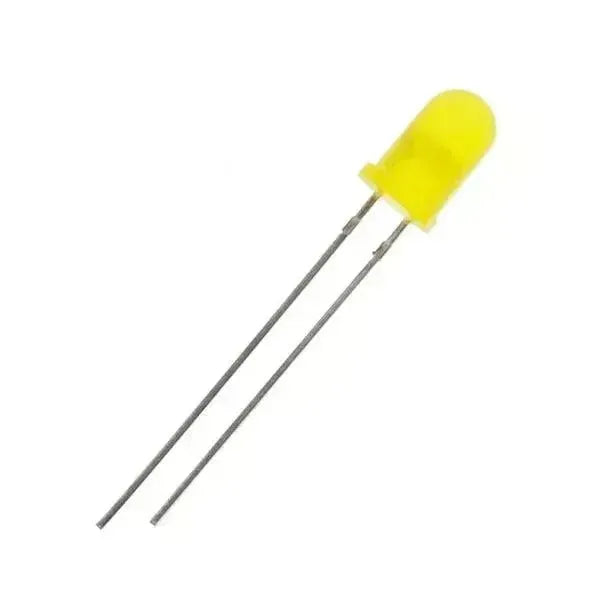
1× LED
-
1× 220 Ω resistor (optional but recommended)
-
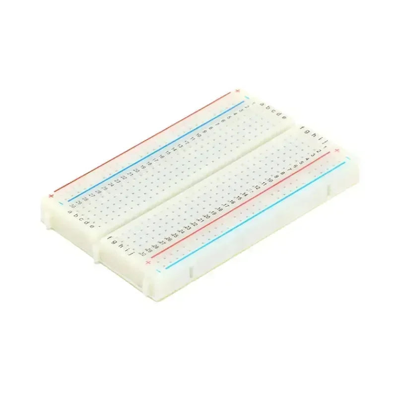
1× breadboard (optional)
Preparation
-
Disconnect the remote device from its power source (battery or USB).
-
Attach the resistor to the longer (positive) lead of the LED, then connect the yellow wire to the other end of the resistor.
-
Connect the opposite end of the yellow wire to a safe GPIO pin (for example, on TLoraV1 you can use GPIO21).
-
Connect the black ground wire from the device’s ground pin (on TLoraV1, this is the end pin next to the RST button) to the shorter (negative) lead of the LED.
-
Restore power to the device.
Validation
By default, a pin may be either “off” or “on” (most commonly “off”). Refer to the steps below for running commands. For example, when using GPIO21, the corresponding mask value is 0x200000.