openelab.de
 openelab.com


Complete development setup for ESP32-S3 SX1262 LoRa Node with Arduino IDE, PlatformIO, and Meshtastic firmware

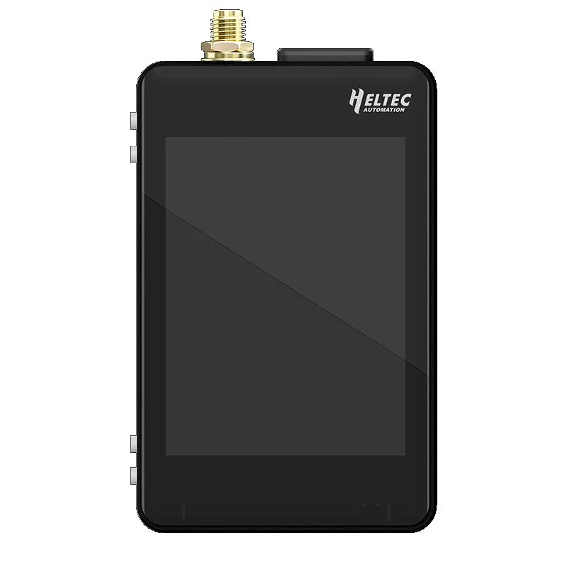
What is HELTEC WiFi LoRa 32 V4?
The HELTEC WiFi LoRa 32 V4 is a powerful IoT development board built around the ESP32-S3R2 dual-core processor and Semtech SX1262 LoRa transceiver. It combines Wi-Fi 4, Bluetooth 5.0, and long-range LoRa communication in a compact form factor, making it ideal for building mesh networks, remote sensor systems, and off-grid communication devices. With 2MB PSRAM, 16MB Flash memory, integrated 0.96" OLED display, and enhanced 28dBm transmit power, the V4 represents a significant upgrade over its predecessor, offering developers unprecedented flexibility for complex IoT applications including Meshtastic deployments and LoRaWAN sensor nodes.


The HELTEC WiFi LoRa 32 V4 maintains pin compatibility with the popular WiFi LoRa 32 V3 while adding significant hardware improvements including a dedicated solar charging interface, GNSS/GPS connector, and upgraded gold-plated pins for enhanced durability. Whether you're prototyping a smart agriculture monitoring system, building a disaster-resilient communication network, or developing low-power environmental sensors, this board provides the connectivity options and processing power to bring your IoT vision to life.
Technical Specifications
The HELTEC WiFi LoRa 32 V4 offers impressive specifications for IoT development:
| Parameter | Specification |
|---|---|
| Microcontroller | ESP32-S3R2 (Xtensa® 32-bit LX7 dual-core, up to 240MHz) |
| LoRa Chip | Semtech SX1262 |
| Frequency Bands | High-power: 863-928 MHz | Low-power: 433, 470-510, 863-928 MHz |
| Max TX Power | High-power: 28±1 dBm | Low-power: 21±1 dBm |
| Receiving Sensitivity | -137 dBm @ SF12, BW=125KHz |
| Wi-Fi | 802.11 b/g/n, up to 150 Mbps |
| Bluetooth | Bluetooth 5.0, BLE, Bluetooth Mesh |
| Memory | 384KB ROM, 512KB SRAM, 16KB RTC SRAM, 2MB PSRAM, 16MB Flash |
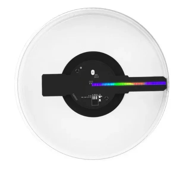
| Display | 0.96" OLED (128×64 pixels, I2C) |
| Hardware Interfaces | 7×ADC, 7×Touch, 3×UART, 2×I2C, 2×SPI |
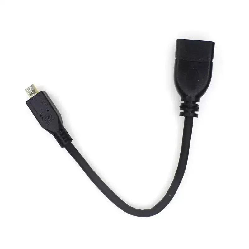
| USB | Type-C (native USB-OTG, no CP2102 required) |
| Battery Interface | SH1.25-2Pin (3.3-4.4V Li-ion, with solar charging support) |
| GNSS Interface | SH1.25-8Pin (GPS module compatible) |
| Antenna Connectors | IPEX 1.0 for LoRa, IPEX 1.0 for 2.4GHz (WiFi/BT) |
| Operating Temperature | -20°C to 70°C |
| Dimensions | 51.7 × 25.4 × 10.7 mm |
| Deep Sleep Current | < 20μA |
HELTEC WiFi LoRa 32 V4 vs V3 Comparison
Understanding the differences between V4 and V3 helps developers decide when to upgrade existing projects or start new designs:
| Feature | V3 | V4 |
|---|---|---|
| MCU | ESP32-S3FN8 | ESP32-S3R2 |
| Flash Memory | 8MB (integrated) | 16MB (external) |
| PSRAM | None | 2MB |
| USB Interface | CP2102 USB-UART | Native USB-OTG |
| LoRa TX Power | 21±1 dBm | 28±1 dBm |
| Solar Input | Not available | SH1.25-2P interface |
| GPS Interface | Not available | SH1.25-8Pin GNSS |
| 2.4G Antenna | Metal spring | FPC + IPEX connector |
| Expansion Pins | 36-pin | 40-pin |
| Pin Plating | Silver-plated | Gold-plated |
| Screen Protection | Partial | Full PC casing |
The V4 maintains backward pin compatibility with V3, meaning existing shields and code should work with minimal modifications. However, the increased transmit power and native USB support require attention when migrating projects.
Hardware Overview
Board Layout

Complete pinout diagram showing all 40 pins, antenna connectors, and interface locations
Key Hardware Interfaces
1. Type-C USB Port
Used for power, programming, and serial communication. The V4 uses native USB-OTG, eliminating the need for CP2102 drivers on most modern systems. Supports USB CDC for serial output.
2. LoRa Antenna (IPEX 1.0)
Connects to the included 868/915MHz antenna. Always attach the antenna before powering on to prevent damage to the SX1262 RF frontend. The high-power version can output up to 28dBm (630mW).
3. 2.4GHz Antenna (FPC/IPEX)
The default FPC antenna is integrated into the screen bracket. For external antennas, remove inductor ① and add a 0Ω resistor at position ② to route to the IPEX connector.
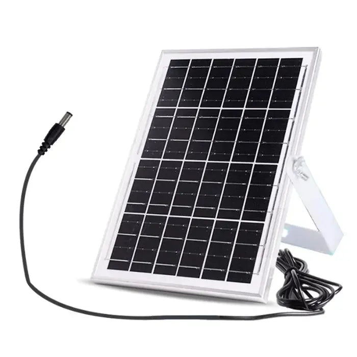
4. Battery & Solar Interface (SH1.25-2Pin)
Supports 3.3-4.4V lithium batteries with integrated charging and protection. The solar input accepts 4.7-6V for autonomous operation. Use the included connector or search for "SH1.25 x 2" replacements.
5. GNSS/GPS Interface (SH1.25-8Pin)
Dedicated connector for GPS modules with individually controllable power. Compatible with common NEO-6M/NEO-M8N modules. The GPS power can be turned off via software to save battery.
6. PRG (USER/BOOT) and RST Buttons
PRG enters bootloader mode when held during reset. RST restarts the ESP32-S3. Both are essential for manual programming recovery.
Pin Definitions
| Function | GPIO | Notes |
|---|---|---|
| OLED SDA | GPIO17 | I2C data for 0.96" display |
| OLED SCL | GPIO18 | I2C clock for 0.96" display |
| OLED RST | GPIO21 | Display reset pin |
| LoRa NSS | GPIO8 | SPI chip select |
| LoRa SCK | GPIO9 | SPI clock |
| LoRa MOSI | GPIO10 | SPI MOSI |
| LoRa MISO | GPIO11 | SPI MISO |
| LoRa DIO1 | GPIO14 | Digital I/O for SX1262 |
| LoRa RST | GPIO12 | LoRa chip reset |
| LoRa BUSY | GPIO13 | SX1262 busy indicator |
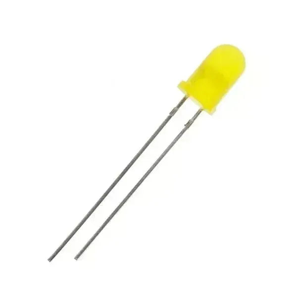
| RGB LED | GPIO38 | WS2812B addressable LED |
| VBAT ADC | GPIO1 | Battery voltage monitoring |
Arduino IDE Setup
Setting up the HELTEC WiFi LoRa 32 V4 for Arduino development is straightforward:
The Arduino IDE is the recommended development environment for HELTEC WiFi LoRa 32 V4. Follow these steps to install the board support package and required libraries.
Step 1: Install Arduino IDE
Download and install the latest Arduino IDE (version 2.0+ recommended). The V4 works with both IDE 1.8.x and 2.x.
Step 2: Add HELTEC ESP32 Board Manager URL
Additional Boards Manager URLs: https://resource.heltec.cn/download/package_heltec_esp32_index.json
Step 3: Install HELTEC ESP32 Development Framework
- Open Boards Manager (left sidebar icon or Tools → Board → Boards Manager)
- Search for
heltec esp32 - Select the latest version (3.0.0 or newer for V4 support)
- Click INSTALL
Step 4: Install HELTEC ESP32 Extended Library
- Open Library Manager (left sidebar icon)
- Search for
HELTEC ESP32 - Install Heltec_ESP32 by HelTec Automation
Step 5: Select Board and Port
Board: "HELTEC ESP32 Series Dev Boards" → "WiFi LoRa 32(V3)" Port: Select your COM port (Windows) or /dev/ttyACM* (Linux/Mac) USB CDC On Boot: "Enabled" (for serial output) Upload Mode: "USB-OTG-CDC (TinyUSB)"
PlatformIO Setup
For professional development, HELTEC WiFi LoRa 32 V4 works excellently with PlatformIO:
PlatformIO is a professional alternative to Arduino IDE, offering advanced features like IntelliSense, debugging, and dependency management. It's particularly useful for larger projects and team development.
Installation Options
- VS Code Extension: Install "PlatformIO IDE" from the VS Code marketplace
-
CLI:
pip install platformio - Standalone: Download from platformio.org
platformio.ini Configuration
Create a new project and use this configuration for HELTEC WiFi LoRa 32 V4:
[env:heltec_wifi_lora_32_V3] platform = espressif32 board = heltec_wifi_lora_32_V3 framework = arduino ; Build options board_build.mcu = esp32s3 board_build.f_cpu = 240000000L ; Upload options upload_protocol = esptool upload_speed = 921600 ; Monitor options monitor_speed = 115200 monitor_filters = esp32_exception_decoder ; Library dependencies lib_deps = heltecautomation/Heltec ESP32 Dev-Boards@^1.1.2 olikraus/U8g2@^2.35.8 sandeepmistry/LoRa@^0.8.0 ; Build flags for V4 build_flags = -D ARDUINO_USB_CDC_ON_BOOT=1 -D CONFIG_USB_OTG_SUPPORTED=1
Project Structure
project/ ├── include/ # Header files ├── lib/ # Custom libraries ├── src/ │ └── main.cpp # Main application ├── test/ # Unit tests ├── platformio.ini # Project configuration └── README.md
Your First Sketch
Let's start with a simple "Hello World" that tests the OLED display and basic connectivity. This verifies your development environment is properly configured.
OLED Hello World Example
#include "Arduino.h" #include "U8x8lib.h" #include "Wire.h" // OLED display pins for WiFi LoRa 32 V4 #define OLED_SDA 17 #define OLED_SCL 18 #define OLED_RST 21 // Initialize OLED display (SSD1306 128x64) U8X8_SSD1306_128X64_NONAME_SW_I2C u8x8(OLED_SCL, OLED_SDA, OLED_RST); void setup() { // Initialize serial for debugging Serial.begin(115200); delay(1000); Serial.println("HELTEC WiFi LoRa 32 V4 Starting..."); // Initialize OLED display u8x8.begin(); u8x8.setPowerSave(0); u8x8.setFlipMode(1); // Flip display 180 degrees // Clear display and set font u8x8.clearDisplay(); u8x8.setFont(u8x8_font_chroma48medium8_r); // Display welcome message u8x8.setCursor(0, 0); u8x8.print("HELTEC V4"); u8x8.setCursor(0, 2); u8x8.print("WiFi LoRa 32"); u8x8.setCursor(0, 4); u8x8.print("ESP32-S3 + SX1262"); u8x8.setCursor(0, 6); u8x8.print("Ready!"); Serial.println("Setup complete!"); } void loop() { // Blink the onboard RGB LED (GPIO38) static uint8_t color = 0; // Simple color cycle switch(color) { case 0: neopixelWrite(38, 255, 0, 0); break; // Red case 1: neopixelWrite(38, 0, 255, 0); break; // Green case 2: neopixelWrite(38, 0, 0, 255); break; // Blue } color = (color + 1) % 3; delay(1000); }
Compiling and Uploading
- Connect your V4 board via USB-C cable
- Select the correct port in Arduino IDE or PlatformIO
- Click Upload (or
pio run --target upload) - Wait for "Leaving... Hard resetting via RTS pin..." message
- Open Serial Monitor at 115200 baud to see debug output
LoRa Code Examples
The SX1262 LoRa transceiver enables long-range wireless communication. Here are practical examples for point-to-point communication.
Basic LoRa Transmitter
#include "LoRa.h" #include "U8x8lib.h" // Pin definitions for HELTEC V4 #define LORA_NSS 8 #define LORA_RESET 12 #define LORA_DIO1 14 #define LORA_BUSY 13 #define LORA_SCK 9 #define LORA_MISO 11 #define LORA_MOSI 10 // OLED setup U8X8_SSD1306_128X64_NONAME_SW_I2C u8x8(18, 17, 21); int counter = 0; void setup() { Serial.begin(115200); while (!Serial); // Initialize OLED u8x8.begin(); u8x8.setFlipMode(1); u8x8.setFont(u8x8_font_chroma48medium8_r); u8x8.clearDisplay(); u8x8.setCursor(0, 0); u8x8.print("LoRa TX"); // Initialize LoRa LoRa.setPins(LORA_NSS, LORA_RESET, LORA_DIO1); // Frequency: 868E6 for EU, 915E6 for US, 433E6 for Asia if (!LoRa.begin(868E6)) { Serial.println("LoRa init failed!"); u8x8.setCursor(0, 2); u8x8.print("Init Failed!"); while (1); } // Configure LoRa parameters LoRa.setTxPower(20); // TX power: 2-20 dBm LoRa.setSpreadingFactor(7); // SF: 6-12 LoRa.setSignalBandwidth(125E3); // BW: 125kHz LoRa.setCodingRate4(5); // CR: 4/5 Serial.println("LoRa TX Ready"); u8x8.setCursor(0, 2); u8x8.print("Ready 868MHz"); } void loop() { Serial.print("Sending packet: "); Serial.println(counter); // Update display u8x8.setCursor(0, 4); u8x8.print("Packet: "); u8x8.print(counter); u8x8.print(" "); // Send packet LoRa.beginPacket(); LoRa.print("Hello #"); LoRa.print(counter); LoRa.print(" from V4!"); LoRa.endPacket(); // Visual feedback neopixelWrite(38, 0, 255, 0); // Green flash delay(100); neopixelWrite(38, 0, 0, 0); // Off counter++; delay(5000); // Send every 5 seconds }
Basic LoRa Receiver
#include "LoRa.h" #include "U8x8lib.h" // Pin definitions (same as transmitter) #define LORA_NSS 8 #define LORA_RESET 12 #define LORA_DIO1 14 #define LORA_BUSY 13 U8X8_SSD1306_128X64_NONAME_SW_I2C u8x8(18, 17, 21); void setup() { Serial.begin(115200); while (!Serial); // Initialize OLED u8x8.begin(); u8x8.setFlipMode(1); u8x8.setFont(u8x8_font_chroma48medium8_r); u8x8.clearDisplay(); u8x8.setCursor(0, 0); u8x8.print("LoRa RX"); // Initialize LoRa LoRa.setPins(LORA_NSS, LORA_RESET, LORA_DIO1); if (!LoRa.begin(868E6)) { Serial.println("LoRa init failed!"); u8x8.setCursor(0, 2); u8x8.print("Init Failed!"); while (1); } // Match transmitter settings LoRa.setSpreadingFactor(7); LoRa.setSignalBandwidth(125E3); LoRa.setCodingRate4(5); Serial.println("LoRa RX Ready"); u8x8.setCursor(0, 2); u8x8.print("Listening..."); } void loop() { // Check for packet int packetSize = LoRa.parsePacket(); if (packetSize) { // Received packet Serial.print("Received packet: '"); String message = ""; while (LoRa.available()) { message += (char)LoRa.read(); } Serial.print(message); Serial.print("' with RSSI "); Serial.println(LoRa.packetRssi()); // Update display u8x8.clearLine(4); u8x8.clearLine(5); u8x8.setCursor(0, 4); // Truncate message if too long if (message.length() > 16) { message = message.substring(0, 16); } u8x8.print(message); u8x8.setCursor(0, 6); u8x8.print("RSSI: "); u8x8.print(LoRa.packetRssi()); u8x8.print(" dBm"); // Visual feedback neopixelWrite(38, 0, 0, 255); // Blue flash delay(200); neopixelWrite(38, 0, 0, 0); } }
Advanced: LoRa with Deep Sleep
For battery-powered applications, use deep sleep between transmissions:
#include "LoRa.h" #include "driver/rtc_io.h" #define LORA_NSS 8 #define LORA_RESET 12 #define LORA_DIO1 14 RTC_DATA_ATTR int bootCount = 0; void setup() { Serial.begin(115200); bootCount++; Serial.println("Boot number: " + String(bootCount)); // Initialize LoRa LoRa.setPins(LORA_NSS, LORA_RESET, LORA_DIO1); if (!LoRa.begin(868E6)) { Serial.println("LoRa init failed!"); esp_deep_sleep_start(); } // Send sensor data LoRa.beginPacket(); LoRa.print("Boot:"); LoRa.print(bootCount); LoRa.print(",VBAT:"); LoRa.print(analogReadMilliVolts(1) * 2 / 1000.0); // Battery voltage LoRa.endPacket(); Serial.println("Packet sent, going to sleep..."); // Configure wake-up timer (60 seconds) esp_sleep_enable_timer_wakeup(60 * 1000000ULL); // Enter deep sleep esp_deep_sleep_start(); } void loop() { // Never reached due to deep sleep }
LoRaWAN Development
The HELTEC WiFi LoRa 32 V4 supports full LoRaWAN protocol implementation:
LoRaWAN enables wide-area network connectivity through gateways. The Heltec ESP32 library includes LoRaWAN support compatible with TTN, ChirpStack, and other networks.
Prerequisites
- Access to a LoRaWAN gateway or public network coverage
- Device EUI, Application EUI, and App Key from your LoRaWAN server
- Heltec ESP32 library with LoRaWAN license (free from Heltec resource center)
LoRaWAN OTAA Example
#include "loramac.h" #include "LoRaWan.h" // Device credentials - replace with your values const char *deviceEui = "XXXXXXXXXXXXXXXX"; // 16 hex chars const char *appEui = "XXXXXXXXXXXXXXXX"; // 16 hex chars const char *appKey = "XXXXXXXXXXXXXXXXXXXXXXXXXXXXXXXX"; // 32 hex chars // LoRaWAN configuration #define LORA_BAND EU868 // EU868, US915, AU915, AS923 #define LORA_CLASS CLASS_A // A, B, or C void setup() { Serial.begin(115200); delay(2000); Serial.println("HELTEC V4 LoRaWAN OTAA"); // Initialize LoRaWAN LoRaWan.init(LORA_BAND, LORA_CLASS, JOIN_OTAA); // Set device credentials LoRaWan.setDeviceEui(deviceEui); LoRaWan.setAppEui(appEui); LoRaWan.setAppKey(appKey); // Join network Serial.println("Joining network..."); if (LoRaWan.join()) { Serial.println("Network joined!"); // Configure data rate (0-5 for EU868) LoRaWan.setDataRate(3); // DR3: SF9, 125kHz } else { Serial.println("Join failed!"); } } void loop() { if (LoRaWan.isJoined()) { // Prepare payload uint8_t payload[4]; // Example: Send temperature and battery int16_t temperature = 250; // 25.0°C (x10 for precision) uint16_t battery = analogReadMilliVolts(1); payload[0] = temperature >> 8; payload[1] = temperature & 0xFF; payload[2] = battery >> 8; payload[3] = battery & 0xFF; // Send uplink (port 1, unconfirmed) Serial.println("Sending uplink..."); if (LoRaWan.send(payload, sizeof(payload), 1, false)) { Serial.println("Uplink sent!"); } else { Serial.println("Uplink failed!"); } // Check for downlink uint8_t downlink[64]; int downlinkLen = LoRaWan.receive(downlink, sizeof(downlink)); if (downlinkLen > 0) { Serial.print("Downlink received: "); for (int i = 0; i < downlinkLen; i++) { Serial.printf("%02X ", downlink[i]); } Serial.println(); } } else { Serial.println("Not joined, retrying..."); LoRaWan.join(); } // Wait for next transmission (respect duty cycle) delay(30000); // 30 seconds }
ABP Activation
For fixed deployments, use Activation By Personalization (ABP):
// Replace with your ABP credentials const char *devAddr = "XXXXXXXX"; // 8 hex chars const char *nwkSKey = "XXXXXXXXXXXXXXXXXXXXXXXXXXXXXXXX"; // 32 hex chars const char *appSKey = "XXXXXXXXXXXXXXXXXXXXXXXXXXXXXXXX"; // 32 hex chars void setup() { LoRaWan.init(LORA_BAND, LORA_CLASS, JOIN_ABP); LoRaWan.setDevAddr(devAddr); LoRaWan.setNwkSKey(nwkSKey); LoRaWan.setAppSKey(appSKey); // ABP doesn't require join - ready immediately Serial.println("ABP mode - ready to send"); }
Meshtastic Firmware
The HELTEC WiFi LoRa 32 V4 is one of the best-supported boards for Meshtastic:
Meshtastic is an open-source mesh networking protocol designed for off-grid communication. The HELTEC V4 is fully supported and offers an excellent platform for Meshtastic nodes.
Why Meshtastic?
- True Mesh: Messages hop through intermediate nodes to reach distant destinations
- Encrypted: AES-256 encryption for all communications
- Multi-hop: Up to 7 hops supported for extended range
- Low Power: Efficient protocol for battery-operated nodes
- Smartphone Integration: iOS and Android apps available
Flashing Meshtastic Firmware
The easiest method is the web-based flasher:
1. Connect Your Device
Plug the V4 into your computer via USB-C. No driver installation needed for most modern systems.
2. Access Web Flasher
Visit flasher.meshtastic.org using Chrome or Edge browser (Web Serial API required).
3. Select Device
Choose "Heltec V3" from the device list (V4 uses the same firmware). Select your region's frequency (EU_868, US_915, etc.).
4. Flash Firmware
Click "Full Erase and Install" for clean installation. Wait for completion - the OLED will display the Meshtastic logo when ready.
Configuration
After flashing, configure your node using the smartphone app or Python CLI:
# Install Meshtastic CLI pip install meshtastic # Connect and configure meshtastic --info # Show node info meshtastic --set owner "MyNode" # Set node name meshtastic --set region EU_868 # Set region meshtastic --set is_router true # Enable router mode # View messages meshtastic --listen
Router vs Client Mode
| Mode | Use Case | Power | Display |
|---|---|---|---|
| CLIENT | Personal messaging device | Battery optimized | Active |
| CLIENT_MUTE | Tracker/sensor node | Low power | Minimal |
| ROUTER | Fixed relay station | Always powered | Optional |
| REPEATER | Simple range extender | Always powered | Off |
Troubleshooting
Common issues with the HELTEC WiFi LoRa 32 V4 and their solutions:
Common Issues and Solutions
Solution: Manually enter bootloader mode:
- Hold the PRG button
- Press and release the RST button
- Release the PRG button
- Try uploading again
Also verify USB CDC On Boot is enabled in Tools menu.
No serial output in monitor
Solutions:
- Set baud rate to 115200 in serial monitor
- Enable "USB CDC On Boot" in Tools menu
- Use proper USB cable (some cables are power-only)
- Try different USB port
LoRa transmission not working
Checklist:
- Antenna connected before power-on
- Matching frequency on TX and RX (868/915/433 MHz)
- Same spreading factor and bandwidth settings
- Verify pin definitions match V4 hardware
OLED display is blank
Solutions:
- Check I2C pins: SDA=GPIO17, SCL=GPIO18, RST=GPIO21
- Verify OLED reset is properly handled in code
- Try setting flip mode:
u8x8.setFlipMode(1) - Check display contrast/brightness settings
High power consumption in sleep mode
Optimization tips:
- Turn off OLED:
u8x8.setPowerSave(1) - Disable RGB LED before sleep
- Put LoRa module in sleep mode:
LoRa.sleep() - Use
esp_deep_sleep_start()instead of delay loops - Verify no floating GPIO pins
Frequently Asked Questions
Common questions about the HELTEC WiFi LoRa 32 V4:
What is the maximum range of HELTEC WiFi LoRa 32 V4?
Range depends on environment and settings:
- Urban: 1-3 km with SF7, up to 5 km with SF12
- Rural/Line-of-sight: 5-15 km achievable
- With external antenna: 20+ km possible
The V4's 28dBm TX power provides approximately 4x range improvement over standard 22dBm modules.
Can I use V3 code on the V4 board?
Yes, the V4 is pin-compatible with V3. Most code will work without modification. However, consider these differences:
- V4 has native USB (no CP2102 drivers needed)
- V4 has more available GPIO pins (40 vs 36)
- Higher TX power on V4 may need regulatory compliance check
- Solar charging and GPS interfaces are V4-specific
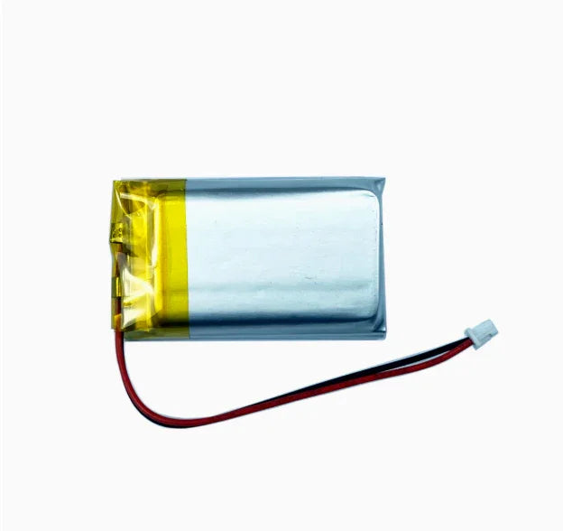
What battery capacity do I need?
For typical applications:
- USB-powered: No battery needed
- Short-term portable: 800-1000mAh Li-ion
- Long-term solar: 2000mAh+ with 5W solar panel
- Deep sleep sensor: 800mAh can last months
The HELTEC 800mAh battery is a good match for most projects.
Is the V4 compatible with Meshtastic?
Yes, the V4 is fully compatible with Meshtastic. Use the "Heltec V3" firmware option in the flasher. The V4 offers advantages for Meshtastic:
- Higher TX power (28dBm) for extended mesh coverage
- Solar charging support for permanent outdoor nodes
- GPS interface for location-aware applications
- More memory for complex routing scenarios
Do I need a license to use LoRaWAN?
It depends on your location and use case:
- ISM Band Operation: No license required for point-to-point LoRa in ISM bands (868MHz EU, 915MHz US, 433MHz Asia)
- LoRaWAN Networks: Generally license-free on public networks like The Things Network
- Heltec Library: Requires free device-specific license from Heltec resource center
- Commercial Deployment: Check local regulations for duty cycles and power limits
What GPS modules work with the V4?
The SH1.25-8Pin GNSS interface supports common modules:
- u-blox NEO-6M: Basic GPS, budget-friendly
- u-blox NEO-M8N: Multi-constellation (GPS+GLONASS)
- u-blox NEO-M9N: Four-constellation support
- ATGM336H: Low-cost alternative
The GPS power can be controlled via software to save battery when location isn't needed.
How do I update the firmware?
Three methods available:
- Arduino IDE: Open new sketch, select board, click Upload
- PlatformIO: Use pio run --target upload
- OTA (Over-The-Air): Use ArduinoOTA or ESP32 HTTP Update
For OTA, the device must be on the same WiFi network as your development machine.
Can I remove the OLED display?
Yes, contact HELTEC sales to order a display-free version. This is useful for:
- Headless sensor nodes
- Lowest power consumption applications
- Custom enclosure designs
- Cost-sensitive deployments
The board functions identically without the display - just skip OLED initialization in your code.
Related HELTEC Products
Expand your IoT ecosystem with these compatible devices:
- HELTEC WiFi LoRa 32 V3 - Predecessor board
- HELTEC WiFi LoRa 32 V2 - Legacy SX1272 version
- HELTEC Wireless Stick V3 - Compact form factor
- HELTEC Wireless Stick Lite - Minimal design
- HELTEC Wireless Tracker - Built-in GPS
- HELTEC Wireless Paper - E-Ink display
- HELTEC 1.9 inch TFT LoRa Node - Larger display
- HELTEC E-Paper 2.9 inch - Large e-ink
- HELTEC HT-CT62 - ESP32-C3 module
- HELTEC Mesh Node T114 - nRF52840 based
- HELTEC MeshPocket - Power bank plus LoRa
- HELTEC MeshSolar - Solar power management
External Resources
Conclusion
The HELTEC WiFi LoRa 32 V4 represents a significant evolution in ESP32-based LoRa development boards. With its powerful ESP32-S3R2 processor, 28dBm transmit power, native USB-OTG, solar charging capability, and expanded memory, it addresses the limitations of previous generations while maintaining compatibility with existing code and shields.
Whether you are building a Meshtastic mesh network, deploying LoRaWAN sensors, or creating custom IoT solutions, the V4 provides the hardware foundation for reliable, long-range wireless communication. The comprehensive Arduino and PlatformIO support ensures a smooth development experience, while the active community and extensive documentation help you overcome any challenges.