openelab.de
 openelab.com


ICL7107 Digital Ammeter DIY Kit
Shipping within 72 hours
*Excluding pre-order items
- • EU & US Delivery: 10 working days
- • Other Countries: 15 working days
Need it faster? Contact us via phone or email for expedited delivery.
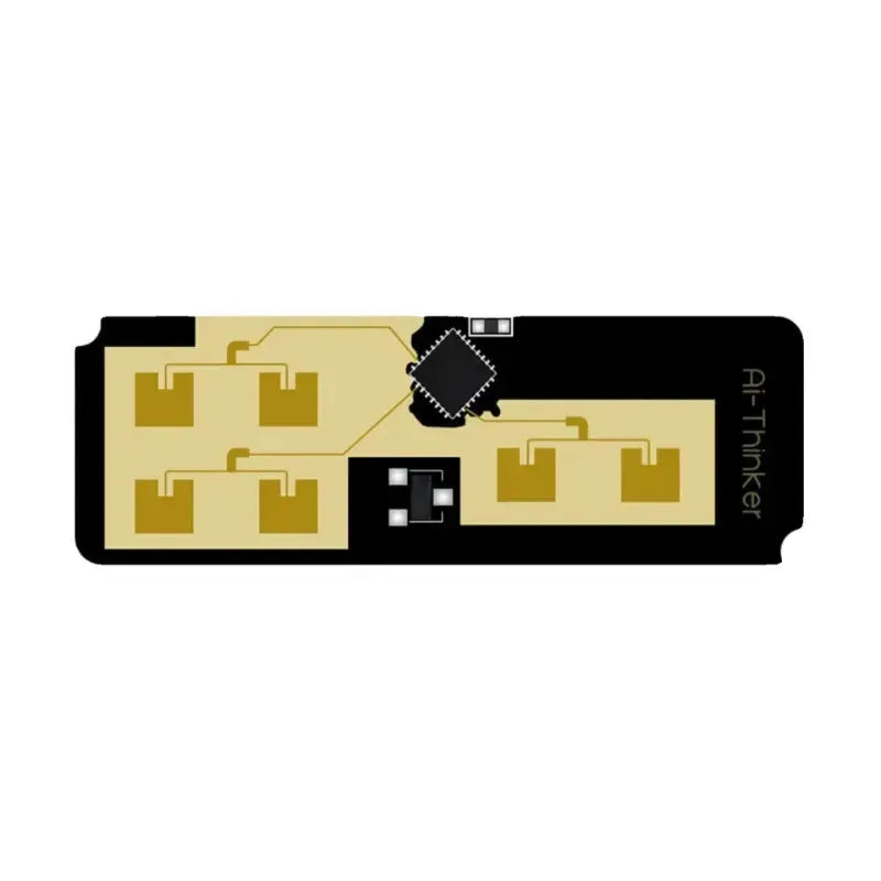
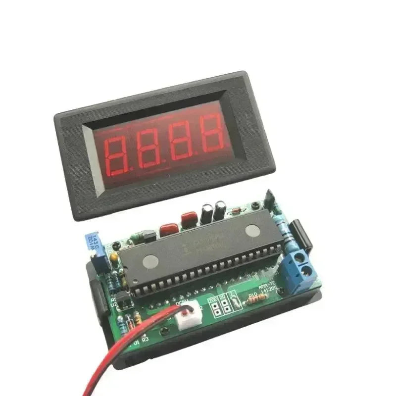
ICL7107 Digital Ammeter DIY Kit
The AMM-TE Ammeter offers fast response, high precision, clear display, intuitive readings, and excellent stability. It features an advanced circuit design with strong anti-interference capabilities, effectively suppressing high-frequency interference. The kit uses high-quality materials, has a refined design, an attractive appearance, and a long service life. It is easy to install and use, making it a reliable choice for users.
Parameters
- Kit Name: Ammeter Kit
- Model: AMM-TE
- PCB Size: 70.6 × 39 mm
- Panel Opening Size: 77 × 40 mm
- Display Window Size: 51 × 24 mm
- Operating Voltage: DC 5V
- Operating Current: 35 mA
- Measurement Accuracy: ±1 mA
- Measurement Range: 0~2A
- Overload Display: Displays “1” or “-1” on the first digit
- Display Color: Red
Assembly Steps
Before soldering, carefully read the instructions below. Some components must be installed in a specific order to ensure successful assembly.
- Solder 2 five-band resistors (color code: red, black, black, brown, brown – both with the same resistance).
- Solder 1 five-band resistor (color code: green, blue, black, red, brown).
- Solder 1 five-band resistor (color code: brown, black, black, yellow, brown).
- Solder 5 four-band resistors.
- Solder 3 diodes of the same model (ensure correct orientation).
- Solder 1 Zener diode (ensure correct orientation).
- Solder 1 inductor (color code: red, red, red, silver).
- Solder 3 ceramic capacitors.
- Install the IC socket as shown in the diagram.
- Install the first pin header in the red-framed area (ensure proper orientation).
- Solder the first pin header and install 4 LED displays (ensure correct orientation).
- After installing the LED displays, trim the excess leads.
- Solder the second pin header (ensure proper orientation).
- Solder 1 transistor and 1 voltage reference chip (ensure correct orientation and match the model).
- Solder 2 CBB capacitors and 2 electrolytic capacitors (ensure correct orientation for electrolytic capacitors).
- Solder 1 sampling resistor.
- Solder 1 potentiometer and 1 polyester capacitor (ensure correct orientation for the potentiometer).
- Solder the power socket and input socket (both with specific orientations).
-
Install the integrated circuit (IC) (pay attention to the direction).
- Insert the power cable (with correct polarity).
- Short-circuit the decimal point selection solder pads as needed.
- Perform tests to verify correct operation after assembly.
- Tighten the four screws to complete the kit assembly.
1. General Shipping Information
- We provide premium shipping methods with a tracking number for each order.
- Shipping addresses must be entered in English without special symbols to help the courier company recognize your address in the system. We will ship strictly according to the shipping address you provided. Please notify us of any address change before your order is marked "Shipped" to avoid parcel loss.
- Please contact our customer service staff immediately if you need to cancel or change an order. Once your order has reached "Shipped" status, it can no longer be canceled or changed in any way. To avoid complications, please recheck your shopping cart before checkout.
- We can ship all in-stock orders within 1 business day after your order has been confirmed.
- All items are inspected before dispatch and are carefully hand-packed.
- With standard courier practice, you need to check the contents of the parcel before signing for your goods. Otherwise, we will not be held responsible for any damage that may have occurred in transit.
🚀 Need Faster Shipping?
If you require expedited shipping (Express), please contact our customer support team at info@openelab.io for a customized quote tailored to your location.
2. Shipping Rates & Options
Our shipping rates are calculated based on the order value and destination. Please refer to the tables below for details.
2.1 Germany (Domestic)
| Shipping Method | Order Value | Cost | Est. Delivery |
|---|---|---|---|
| Deutsche Post | €0 - €50.00 | €4.95 | 2-4 Business Days |
| Deutsche Post | Over €50.00 | Free | 2-4 Business Days |
|
DHL Paket (Faster Delivery) |
€0 - €50.00 | €6.95 | 1-3 Business Days |
|
DHL Paket (Faster Delivery) |
€50.00 - €100.00 | €2.00 | 1-3 Business Days |
|
DHL Paket (Faster Delivery) |
Over €100.00 | Free | 1-3 Business Days |
2.2 European Union (EU)*
*Including:
| Shipping Method | Order Value | Cost | Est. Delivery |
|---|---|---|---|
| Deutsche Post | €0 - €100.00 | €7.95 | 5-9 Business Days |
| Deutsche Post | Over €100.00 | Free | 5-9 Business Days |
|
DHL Paket (Faster Delivery) |
€0 - €100.00 | €15.95 | 3-7 Business Days |
|
DHL Paket (Faster Delivery) |
€100.00 - €250.00 | €7.95 | 3-7 Business Days |
|
DHL Paket (Faster Delivery) |
Over €250.00 | Free | 3-7 Business Days |
2.3 United States
| Region | Shipping Method | Order Value | Cost | Est. Delivery |
|---|---|---|---|---|
|
Continental U.S. (50 States) |
USPS Ground Advantage | €0 - €45.00 | €5.95 | 3-7 Business Days |
| USPS Ground Advantage | Over €45.00 | Free | 3-7 Business Days | |
| USPS Priority Mail | €0 - €45.00 | €16.95 | 1-4 Business Days | |
| USPS Priority Mail | Over €45.00 | €14.95 | 1-4 Business Days | |
|
Non-Continental U.S. (AK, HI, PR, etc.) |
USPS Ground Advantage | €0 - €60.00 | €6.95 | 5-9 Business Days |
| USPS Ground Advantage | Over €60.00 | Free | 5-9 Business Days |
* The regions in the Non-Continental U.S. include: Alaska, American Samoa, Guam, Hawaii, the Marshall Islands, the Northern Mariana Islands, Palau, Puerto Rico, the U.S. Virgin Islands, and all U.S. Armed Forces addresses. The shipping and delivery to these areas are subject to the Non-Continental U.S. shipping rules.
2.4 International (Outside EU)
For specific international destinations, including Switzerland, United Kingdom, and Norway.
| Order Amount | Shipping Cost |
|---|---|
| €0 - €300.00 | €19.95 |
| Over €300.00 | Free |
Important Notice:
- Inventory Status: Please check the inventory status on the product page. Our system displays real-time stock for our Munich and Arlington warehouses. If an item is out of stock in these locations, it will be marked as "Pre-order". You can still place an order for these items.
- Pre-order Fulfillment: For "Pre-order" items, we arrange the most efficient logistics solution to ensure you receive your goods as quickly as possible. Your package may be shipped directly from our Shenzhen warehouse. Alternatively, as part of our standard restocking process, we may transport the goods to our Munich or Arlington warehouse first (typically taking 5-10 business days) before dispatching them to you.
- Split Shipments: If your order contains both in-stock and Pre-order items, we will prioritize shipping the in-stock items from the local warehouse immediately. The remaining Pre-order items will be sent to you in a separate shipment once they are ready.
3. International Warehouse
Our products are stored in our Munich, Arlington, and Shenzhen warehouses to provide more flexible logistics solutions tailored to different regions and customer needs. On each product's description page, we indicate the specific warehouse location to help you better plan your purchase and delivery schedule.
3.1 German Warehouse
For products stored in our warehouse in Munich, we use either Deutsche Post or DHL for shipping, depending on the size of the package. Logistics within Germany are very efficient, with an estimated delivery time of 2-4 business days, ensuring you receive your order quickly and conveniently. For Western EU countries, the estimated delivery time is 4-6 business days. For Eastern EU countries, the estimated delivery time is 6-8 business days.
3.2 US Warehouse
For products stored in our warehouse in Arlington, we use either USPS or UPS for shipping, depending on the size of the package. Logistics within U.S. are very efficient, with an estimated delivery time of 3-7 business days, ensuring you receive your order quickly and conveniently.
3.3 Chinese Warehouse
For Pre-order items or orders fulfilled directly from our Shenzhen warehouse, we utilize YunExpress for reliable international shipping. Given the complexities of international shipping, the estimated delivery time for these packages is around 10 business days, though this may vary slightly due to customs processes or other uncontrollable factors. Otherwise, products will be restocked to our Munich or US warehouses before final delivery, as detailed in the "Important Notice" above.
4. Customs and Taxes
4.1 How are customs handled by OpenELAB for import or export?
For EU Member States: Whether shipped from Germany or China, we cover all import duties and taxes (DDP), ensuring that you receive your package without any additional costs or hassle with customs.
For countries outside of the European Union, such as Switzerland and Norway, you may be subject to import duties, taxes, and/or customs fees charged upon delivery. These fees vary from country to country and are the sole responsibility of the recipient.
⚠️ Refusal of Delivery: If you refuse to pay these fees upon delivery and the package is returned to us, the refund amount will be calculated after deducting the original shipping costs, return shipping costs, and any applicable customs or storage fees.
4.2 How is VAT charged when the Customer places an order from OpenELAB?
In accordance with the newest VAT e-commerce rules in the EU, OpenELAB shall have the right to charge the amount of VAT at checkout. The standard rate of actual VAT applied is subject to the destination country's regulations. No additional VAT will be charged upon delivery for these orders.