openelab.de
 openelab.com


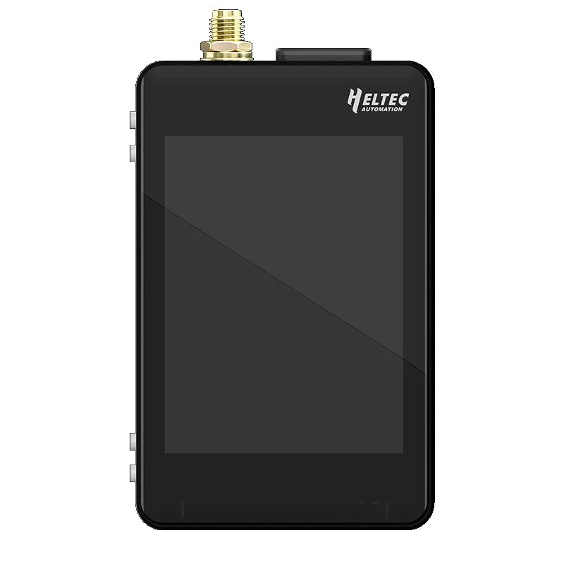


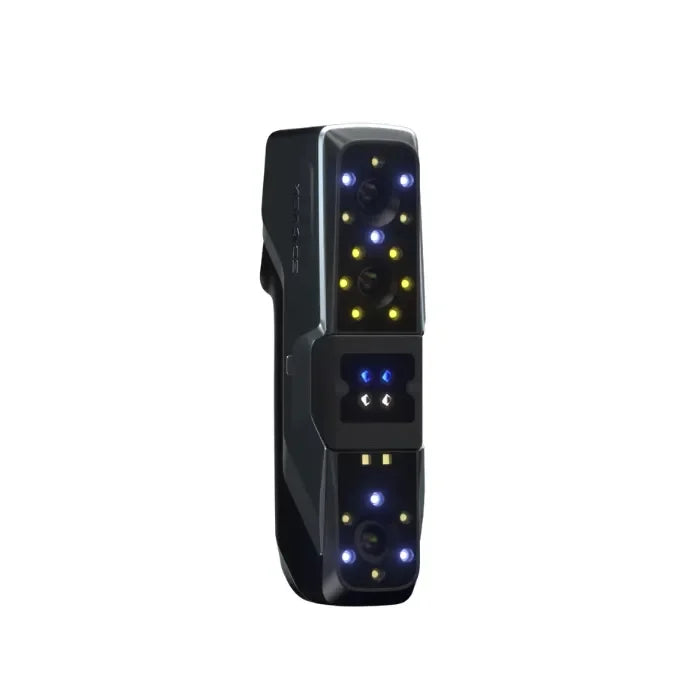
Co je LILYGO T5 E-Paper S3 Pro?
Přehled aktualizací hardwaru a softwaru
| ID | Hardware | Software | Poznámka |
| H752-01 | v1.0-241224 | v1.2_250118 | nejnovější |
| H752 | v1.0-240810 | v1.0-241203 | - |
H752-01 Nová verze:
-
Integrovaný čip pro správu napájení TPS65185 pro řízení e-papíru
-
Podporuje lokální obnovu a nastavení napětí Vcom pro zvýšení hloubky barev displeje
-
Kompatibilní s epdiy v7 pro přímé řízení e-papíru
-
Obsahuje vestavěný GPS modul pro polohovací schopnosti
Datasheety
Modul
| Název | Závislá knihovna |
| epdiy | https://github.com/vroland/epdiy |
| SX1262 | jgromes/RadioLib@6.5.0 |
| BQ25896 | lewisxhe/XPowersLib@^0.2.3 |
| GPS | mikalhart/TinyGPSPlus@^1.1.0 |
| Senzor | lewisxhe/SensorLib@0.2.2 |
| LVGL | lvgl/lvgl@^8.3.11 |
Schéma & 3D
T5_E-Paper-S3-Pro
Začněte s LILYGO T5 E-Paper S3 Pro
PlatformIO
-
Nainstalujte Visual Studio Code a Python, poté klonujte nebo stáhněte repozitář projektu.
-
Ve Visual Studio Code vyhledejte PlatformIO extension a nainstalujte jej.
-
Po instalaci restartujte Visual Studio Code pro aktivaci rozšíření.
-
Otevřete složku projektu. PlatformIO automaticky stáhne všechny potřebné knihovny třetích stran a závislosti. Toto počáteční nastavení může chvíli trvat—prosíme o trpělivost.
-
Po dokončení instalace otevřete konfigurační soubor platformio.ini. V sekci [example] odkomentujte požadovanou rutinu a poté stiskněte Ctrl+S pro uložení souboru.
-
Klikněte na ikonu ve VS Code pro zkompilování projektu. Připojte své zařízení přes USB a ve VS Code vyberte správný COM port.
-
Nakonec klikněte na ikonu pro nahrání programu do Flash paměti zařízení.
Arduino IDE
-
Nainstalovat ten Arduino IDE.
-
Zkopírujte všechny soubory z project/lib/ adresář a vložte je do složky knihoven Arduino (obvykle umístěné v C:\Users\YourName\Documents\Arduino\libraries).
-
Spusťte Arduino IDE, poté přejděte do Soubor → Otevřít v levém horním menu a vyberte soubor příkladu z project/example/xxx/xxx.ino.
-
Nakonfigurujte nastavení Arduino podle potřeby. Po dokončení konfigurace klikněte na tlačítko Nahrát v levém horním rohu Arduino IDE pro kompilaci a nahrání kódu.
| Nastavení Arduino IDE | Hodnota |
| Deska | ESP32S3 Dev Module |
| Port | Váš port |
| USB CDC při spuštění | Povolit |
| Frekvence CPU | 240MHZ(WiFi) |
| Úroveň ladění jádra | Žádný |
| USB DFU při spuštění | Zakázat |
| Vymazat celý Flash před nahráním skici | Zakázat |
| Události běží na | Jádro1 |
| Režim Flash | QIO 80MHZ |
| Velikost Flash | 16MB(128Mb) |
| Arduino běží na | Jádro1 |
| USB Firmware MSC při spuštění | Zakázat |
| Schéma oddílů | 16M Flash(3M APP/9.9MB FATFS) |
| PSRAM | OPI PSRAM |
| Režim nahrávání | UART0/Hardware CDC |
| Rychlost nahrávání | 921600 |
| USB režim | CDC a JTAG |
Struktura složek:
| ├─boards : Některé informace o desce pro konfigurační projekt platformio.ini;
├─data : Obrázkové zdroje používané programem;
├─example : Některé příklady; ├─firmare : `factory` zkompilovaný firmware; ├─hardware: Schéma desky, data čipu; ├─lib : Knihovny použité v projektu; |
Příklady
| -✅ bq25896:Test bq25896 -✅ bq27220:Test bq27220 -✅ display_test:Test zobrazení inkoustové obrazovky. -✅ factory:Program továrního firmwaru. -✅ GPS:Test GPS je potřeba provádět venku. -✅ io_extend:Test čipu pro rozšíření IO. -✅ lora_recv:Test odesílání SX1262 LoRa. -✅ lora_send:Test příjmu SX1262 LoRa. -✅ lvgl_test:Test použití LVGL jako obrazového enginu. -✅ rtc_pcf8563:Test čipu reálného času. -✅ sd_card:Test čtení SD karty. -✅ touch:Test GT911. |
Piny
| // DEFINICE PINŮ DESKY
#define BOARD_GPS_RXD 44 #define BOARD_I2C_PORT (0) #define BOARD_SPI_MISO (21) #define BOARD_TOUCH_SCL (BOARD_SCL) #define BOARD_RTC_SCL (BOARD_SCL) #define BOARD_SD_MISO (BOARD_SPI_MISO) #define BOARD_LORA_MISO (BOARD_SPI_MISO) #define BOARD_BL_EN (11) // ED047TC1 --- e-ink paper #define EP_D7 (8) // PCA9535 |
Test

Jak stahovat programy přes flash_download_tool ?
-
Stáhnout a nainstalovat the Flash Download Tools.
-
Připojte zařízení přes USB. T5_E-Paper_S3_Pro vstoupí do režimu stahování podle těchto kroků:
-
Stiskněte a držte tlačítko BOOT
-
Při držení BOOT stiskněte a uvolněte tlačítko RST na zadní straně
-
Nakonec uvolněte tlačítko BOOT
-

-
Spusťte Flash Download Tools a proveďte výběry zobrazené na referenčním obrázku.

-
Vyberte program, který chcete stáhnout, a poté klikněte na tlačítko Start pro zahájení flashování, jak je znázorněno.

-
Jakmile je stahování dokončeno, stiskněte tlačítko RST pro restartování zařízení.