openelab.de
 openelab.com


Preparation of Hardware Components
-
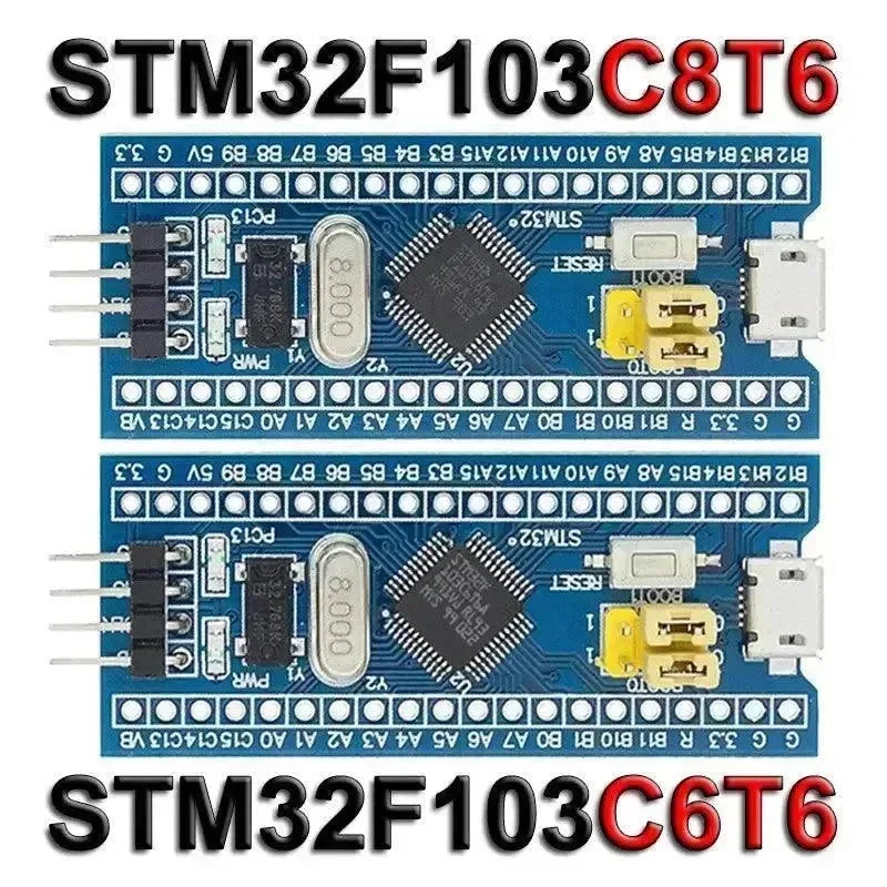
Selection of STM32 Development Board: Choose an appropriate STM32 development board, such as STM32F103C8T6 or other compatible models.
-
Programming Tool: The DAPLINK, a replacement for the JLINK OB/STLINK STM32 Burner, can be utilized as a programming tool to upload the program to the STM32 microcontroller.
-
Debugging Tool: The DAPLINK can also serve as a debugging tool, aiding in the identification and resolution of issues in code execution.
-
External Devices and Sensors: If interaction with peripherals (e.g., sensors, displays, etc.) is necessary, it may be essential to procure these hardware modules.
-
Power Supply: Ensure the adequate power supply for the development board, either through USB power or an external power source.
Software Environment Configuration
- Commonly used development environments for STM32 development include Keil MDK, IAR Embedded Workbench, and STM32CubeIDE, which is officially provided by STMicroelectronics and is free of charge. STM32CubeIDE is suitable for both beginners and professional developers.
-
STM32CubeMX is a configuration tool provided by STMicroelectronics to facilitate the generation of initialization code. This tool allows for the configuration of peripherals, clock trees, pin assignments, and automatically generates related code to streamline the development process.
-
STM32 development typically involves the use of the C programming language, so a basic understanding of C programming is necessary.
Project Development Steps
-
Project Creation
-
Open STM32CubeMX or STM32CubeIDE, create a new project, and select the STM32 chip model or development board used.
-
Pin Configuration
-
Configure the pins of the chip in STM32CubeMX. According to the project requirements, you can select the enabled peripherals (such as GPIO, UART, I2C, SPI, etc.) and assign them to specific pins.
-
Peripheral Initialization
-
STM32CubeMX will generate the corresponding initialization code according to the peripherals you configured, and you can develop specific functions based on the generated code.
-
Writing Application Code
-
Write your application code in the IDE, for example:
-
Configuring and reading sensor data
-
Control GPIO for LED light on/off
-
Use UART for serial communication
-
Use timer for periodic tasks
-
-
Compile and burn
-
After writing the code, compile it in the IDE to make sure there are no errors. Use the burn tool to burn the compiled binary file (e.g. .hex or .bin file) into the STM32 microcontroller.
-
Debugging and Optimization
-
If there is a problem with the code, you can use the debugging tools in the IDE (e.g., breakpoints, single-step execution, etc.) to check the operation of the code.
-
During debugging, you can also use the serial port to print debugging information to check whether the program logic is correct.
Project Debugging and Optimization
- Debugging Tools
- Use the DAPLINK debugging function to perform single-step debugging, variable viewing, and other operations through the SWD interface.
- Serial port debugging
- Use the UART serial port to output debugging information to the PC (via serial port tools such as PuTTY or SecureCRT) to help analyze the program running status.
- Logic analyzer and oscilloscope
- For applications with high timing requirements (such as SPI, I2C communication, etc.), you can use a logic analyzer or oscilloscope to check the waveform and communication timing.
Program Burning
-
DAPLINK is burned in via the SWD interface.
-
UART Serial Port Burning by using the Flash Loader tool.
-
USB DFU mode burner burns directly through the USB interface (requires STM32 models with DFU support).
Test and Iteration