openelab.de
 openelab.com


Introduction
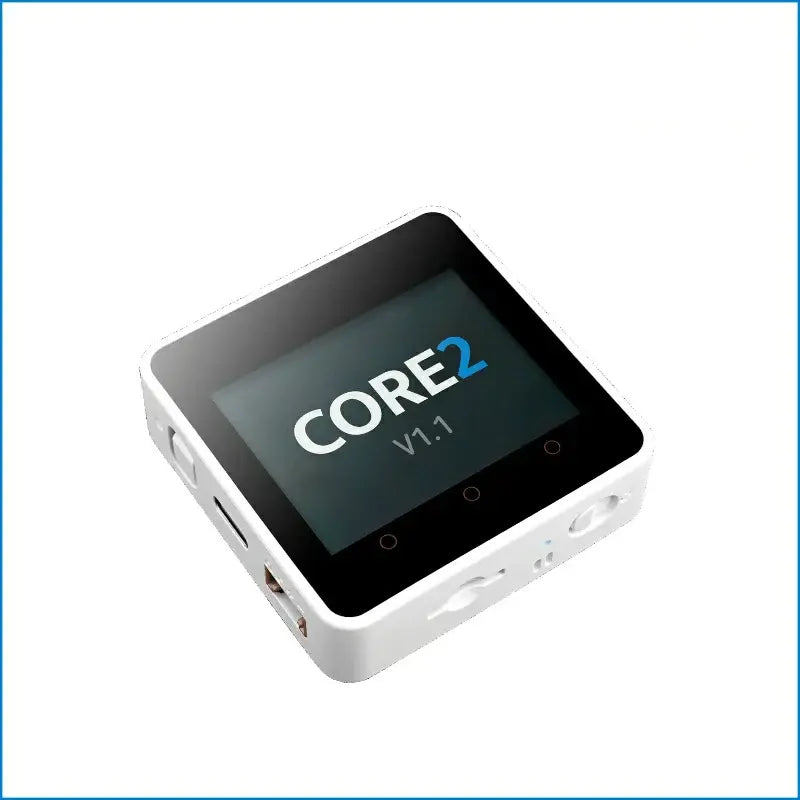
First Meeting M5Stack Core2
The M5Stack Core2 supports multiple programming platforms like Arduino, MicroPython, and M5Stack UIFlow, making it versatile for various IoT projects, including smart home devices, educational tools, and rapid prototyping. Its modular design allows for easy expansion with other M5Stack modules, enhancing its functionality for diverse applications.
Key Features and Capabilities
Processor
Dual-core ESP32-D0WDQ6-V3, running up to 240MHz.
Memory
-
16MB Flash memory
-
8MB PSRAM
Wireless Connectivity
-
WiFi 802.11 b/g/n
-
Bluetooth 4.2 BLE
User Interface
-
6 programmable touch buttons
-
Vibration motor for haptic feedback
Sensors
-
6-axis IMU (MPU6886) for acceleration and gyroscope data
Audio
-
Integrated speaker
-
I2S digital audio interface
Power Management
-
AXP192 PMU for battery management
-
Supports USB Type-C charging
-
Built-in LiPo battery
RTC
-
Real-Time Clock for accurate timekeeping
Main Content of This Article
The primary goal of this article is to provide a comprehensive overview of the M5Stack Core2, an innovative IoT development kit based on the ESP32 microcontroller. We aim to:
-
Educate readers on hardware specifications, including its processing power, memory, connectivity options, and integrated sensors.
-
Highlight unique features like the touch screen interface, haptic feedback, and the modular design that allows for project expansion.
-
Guide users through the various programming environments (Arduino, MicroPython, UIFlow) supported by M5Stack Core2, offering insights into which might be best for different types of projects.
-
Demonstrate potential applications by showcasing real-world examples where the M5Stack Core2 can be utilized, from educational tools to smart home devices.
-
Assist in decision-making for hobbyists, educators, and professionals considering this device for their IoT projects by discussing its strengths, limitations, and how it compares to other similar platforms.
By the end of this article, readers will have a thorough understanding of what the M5Stack Core2 offers, how to leverage its capabilities, and whether it fits their specific needs in the realm of IoT development.
What is M5Stack Core2?
Detailed Explanation of M5Stack Core2
The M5Stack Core2 is an advanced ESP32-based IoT development kit designed for both beginners and experienced developers. It features a dual-core ESP32-D0WDQ6-V3 processor running at up to 240MHz, with built-in WiFi and Bluetooth capabilities. This kit includes 16MB of Flash memory and 8MB of PSRAM for enhanced performance.
Key highlights of the Core2 include a 2-inch capacitive touch screen that allows for intuitive user interaction, programmable touch buttons, and a built-in vibration motor for haptic feedback. It also has an integrated RTC (Real-Time Clock) module for accurate timekeeping, and power management is handled by the AXP192 chip, which controls battery consumption efficiently. Additional features include a speaker, an I2S digital audio interface for clear sound output, and a 6-axis IMU sensor on the back for motion detection.
Applicable Groups
Hobbyists and DIY Enthusiasts
Individuals passionate about electronics, robotics, and IoT projects looking for an all-in-one solution to experiment with.
Educators and Students
Teachers seeking engaging tools for teaching programming, electronics, and IoT concepts, as well as students learning these subjects.
IoT Developers
Professionals or enthusiasts developing IoT solutions who need a compact, powerful platform with extensive connectivity options.
Makers and Hackerspaces
Communities or individuals involved in maker fairs, hackathons, or collaborative spaces where quick prototyping is essential.
Product Designers
Those prototyping new smart devices or integrating IoT into existing products, needing a versatile platform for development and testing.
Artists and Interactive Installations
Creatives using technology to enhance art installations or interactive exhibits with sensors, displays, and connectivity.
Difference Between M5Stack Core2 and M5Stack Core2 V1.1
| Feature | M5Stack Core2 | M5Stack Core2 V1.1 |
| Power Management | AXP192 Chip | AXP2101 + INA3221 (Upgraded Power IC) |
| Power Indicator Color | Green | Blue |
| RTC (Real-Time Clock) | Built-in, but no dedicated battery for RTC |
Includes a dedicated battery for RTC to maintain time when powered off |
| USB Chip | CH9102F | Same, but driver installation might differ due to hardware version |
| General Design | Classic Core2 design | Iterative version with the same form factor but updated internals |
| Compatibility | Compatible with M5GO Bottom for additional features | Compatibility with modules might require removing or using a specific Bottom2 for full functionality |
| Programming Environment | Supports Arduino, MicroPython, UIFlow | Same support, no change in programming environment |
| Touch Screen | 2-inch capacitive touch screen | Same, with no change in screen specifications |
| Vibration Motor | Included for haptic feedback | Included, no change |
| Memory & Processor | ESP32-D0WDQ6-V3, 16MB Flash, 8MB PSRAM |
Same specifications |
M5Stack Core2 Hardware
M5Stack Core2 Screen size and resolution
-
Screen Size: 2 inches
-
Resolution: 320 x 240 pixels
M5Stack Core2 Processor, Memory, and Storage
-
Processor: Dual-core ESP32-D0WDQ6-V3, operating at up to 240MHz.
-
Memory:RAM: 8MB PSRAM (Pseudo Static RAM)
-
Storage:Flash Memory: 16MB
Connectivity Options
-
WiFi: 802.11 b/g/n, enabling wireless networking for IoT projects.
-
Bluetooth: Version 4.2 BLE (Bluetooth Low Energy), for low-power, short-range wireless communication.
Sensors and Peripherals
Sensors
-
6-Axis IMU (Inertial Measurement Unit):Combines a 3-axis accelerometer and a 3-axis gyroscope for motion sensing. It uses the MPU6886 sensor, which provides data for orientation, acceleration, and rotation.
These sensors are the primary ones built into the M5Stack Core2. However, the device's design allows for expansion via various M5Stack modules and GROVE ports, which can add additional sensors like:
Temperature sensors
Humidity sensors
Light sensors
Proximity sensors
Pressure sensors
Magnetic field sensors (compass)
etc.
Peripherals
-
Programmable Touch Buttons:The screen includes three capacitive touch buttons, which can be programmed for various functions or user inputs.
-
Microphone:An onboard microphone allows for sound detection or voice command capabilities.
-
Speaker:Integrated for audio output, useful for alarms, notifications, or music playback.
-
Vibration Motor:Provides haptic feedback, enhancing user interaction in applications like games or notifications.
-
RTC (Real-Time Clock):A built-in RTC module for keeping track of time, even when the device is powered off, ensuring accurate timekeeping for scheduling or time-based operations.
-
Power Management IC (PMIC):The AXP192 chip manages power distribution, battery charging, and voltage regulation, which is crucial for maintaining efficiency and extending battery life.
-
USB Type-C Port:For power, programming, and data communication. It supports USB OTG for connecting external devices like keyboards or mice in some configurations.
-
MicroSD Card Slot:Allows for additional storage, ideal for logging data, updating firmware, or storing media.
Power Supply and Battery Life
Power Supply
-
Input Voltage: 5V via USB-C port for charging and powering the device.
-
Power Management: The power supply is managed by the AXP192 chip in the original Core2, and by the AXP2101 + INA3221 in the Core2 V1.1, allowing for efficient power consumption control.
-
Battery Charging: Supports charging through the USB-C port, with the possibility of external power options through specific pins if configured correctly.
Battery
-
Battery Included: A 390mAh LiPo battery is built into the Core2, providing power when disconnected from external sources.
-
Battery Extension: For extended battery life, users can add external battery modules like the M5GO Bottom2 (which includes an additional 500mAh battery) or stack multiple battery modules since they are parallelable.
Battery Life
-
Usage Duration: Battery life varies significantly based on usage.Idle or Low Power Modes: With the screen off and in low power modes, it can last for hours or even days, depending on how frequently it wakes up or the depth of sleep mode used.Active Use: With the screen on and actively running programs, especially those utilizing WiFi or Bluetooth, battery life might last from a few hours to around 5-6 hours, depending on factors like screen brightness, sensor usage, and processing load.
-
Sleep Modes: ESP32's deep sleep mode can dramatically extend battery life, potentially for weeks or months if the device only needs to wake up occasionally, like for data logging or periodic WiFi checks.
-
Enhancements: Users often report that they can extend battery life through software optimizations, such as dimming the screen, reducing sensor polling rates, or using efficient power management strategies like deep sleep for non-active periods.
Additional Notes
-
Power Indicator: There's a built-in LED (green in original, blue in V1.1) that indicates power status and can be programmed for custom notifications.
-
RTC Battery: In the V1.1 model, there's an additional small battery for the RTC, ensuring timekeeping even when the main battery is depleted or removed.
Software and Development
Supported programming languages
-
C/C++ (used with Arduino IDE)
-
Python (MicroPython flavor for ESP32)
-
JavaScript (for certain web-based applications, not direct device programming but can interact through web interfaces or node-red).
Supported programming platforms
-
Arduino: This is one of the most popular platforms for the ESP32. The Arduino IDE with ESP32 support allows you to write and upload code to M5Stack Core2 using C/C++.
-
MicroPython: An implementation of Python 3 for microcontrollers, MicroPython is well-suited for those who prefer Python's syntax. It provides an interactive REPL (Read-Eval-Print Loop) for immediate code testing, making it particularly educational-friendly.
-
UIFlow: This is M5Stack's own visual programming language or block-based programming environment similar to Scratch or Blockly. It's designed to be very user-friendly, allowing you to program the Core2 by connecting blocks representing code functions. UIFlow can generate MicroPython or Arduino code behind the scenes, which can then be further edited or used directly.
Each of these environments offers different advantages:
-
Arduino provides a more traditional microcontroller programming experience with access to a vast ecosystem of libraries.
-
MicroPython makes it easier for beginners or Python enthusiasts to start with hardware programming, offering a more readable and interactive coding experience.
-
UIFlow is excellent for rapid prototyping, education, or for those who might not have extensive coding experience but want to create functional IoT devices.
These platforms are not mutually exclusive; you can start with one and transition or use another for different aspects of your project, leveraging their unique features to suit your development needs.
Development environment setup
Installing Arduino IDE
Visit the Arduino.cc and click software, or you can click HERE.
Download Arduino IDE, install it.
Installing Board Management
The Board Manager URL is employed for the purpose of indexing the development board information for a particular platform. In the Arduino IDE menu, select File -> Preferences

Copy the M5Stack board management URL below into the Additional Board Manager URLs: field, and save.

In the sidebar, select Board Manager, search for M5Stack, and click Install

Selecting the Development Board
Depending on the product used, select the corresponding development board under Tools -> Board -> M5Stack -> {Product Name}.

Quick Start Guide for M5Stack UIFlow 2.0 Web IDE
What is M5Stack UIFlow
UIFlow2 is a user-friendly graphical programming IDE that offers seamless wireless and wired program push, program click and run functionality, eliminating the need for repeated compilations. It seamlessly integrates with over 100 M5 hardware peripherals and sensors, enabling effortless addition and expansion with a single click. This feature empowers product prototype construction and accelerates the development process, ultimately leading to enhanced productivity and efficiency. In this tutorial, we will demonstrate how to burn the UIFlow 2.x version firmware on your M5Stack device and use the UIFlow Web IDE for secondary development of the product.
Before programming with UIFlow, there are a few preparatory steps to take:
-
Install the M5Burner firmware burning tool.
-
Use M5Burner to burn the firmware for the corresponding device, log in to your account, and configure Wi-Fi connection for the device.
-
Open the UIFlow Web IDE 2.0 version, select the appropriate online device option, and click to connect.
-
Drag and drop blocks to edit the program, and click the Run button to debug the program.
Additional Information:
M5Burner is a unified firmware burning tool introduced by M5Stack. It allows users to easily burn UIFlow firmware and write configuration information such as Wi-Fi settings during the burning process.
Install M5Burner
M5Stack Community Account
In order to access the M5Burner and UIFlow 2.0/1.0 software, you will need to register an M5Stack Community account. Please be advised that this account can also be used to log in to the M5Burner and UIFlow 2.0/1.0 login page. To register for an M5Stack Community account, please click the 'Register' button on the M5Burner software, UIFlow 2.0/1.0 software, or the web version.
Firmware Burning & Running Programs
USB Driver Installation
Port Selection
In order to connect the device to the computer, please use a USB cable. Then, click the Burn button for the relevant firmware in M5Burner. You will then need to enter the Wi-Fi information and select the correct device port.

Firmware Burning
Connect the device to the computer via a USB cable, select the Burn button for the corresponding firmware in M5Burner, and fill in the Wi-Fi configuration that the device is pre-connected to, including Wi-Fi SSD and Wi-Fi Password, as well as other device configurations that need to be added or modified.


Open UIFlow
Click https://uiflow2.m5stack.com, open the M5Stack UIFlow 2.0
Click the device bar in the lower right corner, you can find your new device like this:


You can now use M5Stack UIFlow normally.
Libraries and SDKs
Libraries
SDK
How to connect M5Stack to Arduino IDE
Connect your M5Stack Core2 and your computer.
Open Arduino IDE, click tools-Board-M5Stack-M5Core2

Choose the right Port, change your upload speed to 1500000

Basic programming examples
Click File-Examples-M5Core2, you can find the basic programming examples.
When you finish verifying, you can upload the code into your M5Stack Core2.

Unboxing and Setup
What's in the box
-
1x Core2 V1.1
-
1x Type-C USB(20cm)
-
1x HEX KEY

The back of the M5Stack Core2 features the following key components:
-
ESP32-based with built-in Wi-Fi
-
16M Flash and 8M PSRAM
-
-
Built-in speaker, power indicator, vibration motor, RTC, I2S amplifier, power button.
-
TF card slot (up to 16GB)
-
Built-in lithium battery with power management chip
-
Independent small board with a 6-axis IMU and PDM microphone
-
M-Bus Socket & Pins

Once you open the back cover labeled with ‘Core2’ on the left side, you will find the MIC chip (SPM1423), the IMU chip (MPU6886, which includes a 3-axis gyroscope and 3-axis accelerometer), and the pins for connections.

M5Stack Core2 Factory Firmware
The M5Stack Core2 Factory Firmware page provides a comprehensive overview of the device's capabilities. It displays key information such as the MPU6886 chip, real-time clock, battery level, and various settings options. The page also includes features like power on/off functionality, Wi-Fi connection status, and a timer function. Additionally, it allows for the display of images and music stored on the SD card and provides a visual representation of the current volume level. This page serves as an intuitive interface for managing the device's essential functions and monitoring its performance.

System Function Testing
The system supports I/O connection testing, smart motor testing, buzzer testing, and TFT screen functionality testing. These tests help ensure that all components are working correctly, allowing users to verify the device’s key features and functionality.

Support Wi-Fi
On the Wi-Fi page, the M5Stack Core2 displays available Wi-Fi networks nearby, sorted by signal strength. Users can easily view and select the best network for connection, ensuring optimal signal quality and stability. This feature enables the device to quickly connect to a network, providing reliable support for IoT applications and remote operations.

M5Stack Core2 Examples
UIFlow Projects
Today I use the M5Stack 8ENCODER and M5Stack Core2 to show you how to use M5Stack UIFlow
Connect
First of all, connect M5Stack Core2 and computer with Type-C cable, and connect M5Stack Core2 and 8ENCODER with Grove cable
Because the 8ENCODER unit has 8 channels, we got 9 labels on the M5Stack Core2 screen like this:

Add Unit
Next, add a unit, find 8Encoder and choose the Bus to I2C

Setup
Init I2C SCL to 33, SDA to 32, freq to 100K
Init encoder8_0 I2C address to 0x41

Loop
M5Stack 8Encoder channel value set

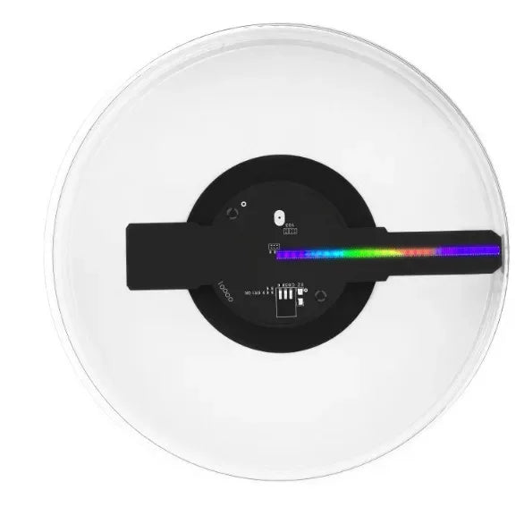
M5Stack 8Encoder channel RGB LED color set

Let's made a prototype of a ringing combination lock

If channel 1 value = channel 2 value, channel 3 value = channel 4 value
Do label8 text ‘Right’, and buzzer loud remind us
Else, label8 text 'Wrong', buzzer quiet
Let's upload the code and find out what will happen


And we can handle more complex logic. Have fun with your M5Stack Core2.
Cool DIY Projects for M5Stack Core2
M5Stack Core2 and Home Assistant
Integration with Home Assistant
Because M5Stack Core2 used an ESP32 chip, we can use ESPHome to connect M5Stack and Home Assistant.


Setting up M5Stack Core2 as a home automation controller
Install ESPHome in Home Assistant
-
If not already installed, navigate to Home Assistant's Settings > Add-ons > Add-on store.
-
Search for ‘ESPHome’ and install it. Once installed, start the add-on.
Create a New Device in ESPHome
-
After the ESPHome add-on is running, go to the ESPHome page in your Home Assistant instance.
-
Click New Device at the bottom right, then Continue.
-
Name your device, e.g., ‘m5stack-core2’, and select ESP32 as the platform, then choose M5Stack Core or M5Stack Core2 if listed (the exact naming might vary based on the ESPHome version).
Configure ESPHome for M5Stack Core2
-
Here's an example YAML configuration you might use for the M5Stack Core2:
esphome:
  name: m5stack-core2
  platform: ESP32
  board: m5stack-core-esp32

wifi:
  ssid: "Your_WiFi_SSID"
  password: "Your_WiFi_Password"

# Enable fallback hotspot (captive portal) in case wifi connection fails
ap:
  ssid: "M5Stack-Core2 Fallback Hotspot"
  password: "Your_AP_Password"

logger:
api:
ota:

sensor:
  - platform: axp192
    address: 0x34
    i2c_id: bus_a
    update_interval: 30s
    battery_level:
      name: "M5Stack Core2 Battery Level"

# Example for using the screen (if supported in your ESPHome version)
display:
  - platform: ili9341
    model: M5STACK_CORE2
    cs_pin: GPIO5
    dc_pin: GPIO15
    reset_pin: GPIO33
    backlight_pin: GPIO32
    lambda: |-
      it.print(0, 0, id(my_text_sensor).state.c_str());

# If you want to use buttons or other features
button:
  - platform: gpio
    name: "Button A"
    pin:
      number: GPIO39
      inverted: true
    id: button_a
✔ Copied!
Note: The exact configuration for the display might not be fully supported or might require additional setup, as there have been mentions of limited support for the Core2's screen in ESPHome. You might need to look for community contributions or external libraries for full functionality.
Compile and Upload the Firmware
-
Click Install in the ESPHome interface to compile the YAML configuration into firmware and flash it to the M5Stack Core2. Make sure your device is in flashing mode (often by holding the power button or reset button during startup).
Integrate with Home Assistant
-
Once the device connects to your WiFi, Home Assistant should automatically discover it if you're using the native API. If not, you can manually add it in Configuration > Integrations > Add Integration, searching for ‘ESPHome’ and entering the device's hostname or IP.
Troubleshooting and Additional Features
-
If the display isn't working or other components like sensors or buttons aren't recognized, you might need to check community forums or GitHub for updates or custom configurations. There are discussions about needing to manually add support for certain components of the Core2 like the power management chip (AXP192) or the screen.
Battery Management
The M5Stack Core2 has a built-in power management system; ensures you configure it correctly for battery monitoring and power saving features.
Custom Components
For features not natively supported, you might need to create or use custom components or look into alternatives like OpenHASP for display control.
Remember, the ESPHome support for M5Stack Core2, especially regarding the display, might evolve, so keeping your ESPHome and Home Assistant updated could help with compatibility and feature availability.
Troubleshooting and FAQs
Common issues and solutions
Q1: What is the spec of M5Stack Core2?
A1:
The M5Stack Core2 is a feature-rich ESP32 development board designed for IoT and embedded applications, powered by the ESP32 D0WDQ6-V3 dual-core MCU with 16MB Flash and 8MB PSRAM. It comes with a 2.0-inch capacitive touchscreen, Wi-Fi connectivity, and a 390mAh rechargeable battery managed by the AXP192 power chip, ensuring efficient power control. Additional features such as a USB Type-C interface, TF card slot, built-in RTC module, vibration motor, I2S digital audio interface, and programmable capacitive touch buttons make M5Stack Core2 an ideal choice for developers working on smart devices, home automation, and interactive electronics projects.
Q2: What is the resolution of the M5Stack Core2 display?
A2:
The M5Stack Core2 features a 2.0-inch capacitive touchscreen with a resolution of 320x240 pixels.
Q3: What is the baud rate of M5Stack Core2?
A3:
The default baud rate for the M5Stack Core2 is typically set to 115200 bps for serial communication. However, it can be adjusted in the code to other values depending on the requirements of your project.
Q4: Why is my memory card not reading on M5Stack Core2, and how can I fix it?
A4:
To enhance the memory card reading capability on the M5Stack Core2, you can use the following code to configure the GPIO pins and improve the memory interface:
for (auto gpio : (const uint8_t[]){18, 19, 23}) {
   *(volatile uint32_t*)(GPIO_PIN_MUX_REG[gpio]) |= FUN_DRV_M;
   gpio_pulldown_dis((gpio_num_t)gpio);
   gpio_pullup_en((gpio_num_t)gpio);
}
✔ Copied!

This code configures the specified GPIO pins (18, 19, 23) by enabling the necessary pull-up resistors and adjusting the drive strength, which can help improve memory card reading performance.
Q5: How do we detect the power level of core2?
A5:
To detect the power level of the M5Stack Core2, you can use the following code that utilizes the Core2 API to retrieve the battery voltage:
#include

void setup() {
  M5.begin();
}

void loop() {
  Serial.printf("Battery Voltage: %f\n", M5.Axp.GetBatVoltage());
  delay(500);
}
✔ Copied!
This code reads the battery voltage and prints it to the serial monitor every 500 milliseconds. Make sure to refer to the M5Core2 API documentation for more detailed functions and configurations related to power management.
Q6: How can I display pictures on the M5Stack Core2 using C language?
A6:
To display a 320x240 pixel JPG image named
logo.jpg on the M5Stack Core2, follow these steps:-
Create the image: Prepare a 320x240 pixel JPG image called
logo.jpg. -
Convert the image: Download the source files, unzip them, and open the folder. Execute the
.\conver.ps1script in the terminal to convert the image into a binary format compatible with Core2. -
Replace the image data: After conversion, take the resulting binary data and replace the content in the array of the provided source file.
-
Upload the program: Open the
drawImageData_core2_Pure.inofile, and insert the converted binary data into the array. Upload the program to the M5Stack Core2.


Once the program is uploaded, the image will be displayed on the screen as shown in the example.
Make sure to refer to the official documentation for additional instructions on handling images and their binary formats.
Tips and tricks for using M5Stack Core2
General Tips
Battery Management
Use the AXP192 chip for power management. Monitor battery levels through the M5Stack Core2 library or ESPHome configurations to manage power consumption efficiently.
Firmware Updates
Regularly check for and update the firmware of your M5Stack Core2 to benefit from new features, performance improvements, and security patches. Use the M5Burner tool for this.
Custom Boot Logo
Personalize your device by setting a custom boot logo using the M5Burner tool. This can make your device uniquely yours or reflect a project's theme.
Hardware Utilization
Screen Brightness
Adjust screen brightness programmatically using the AXP192 chip to save battery. Lower brightness for less critical operations or when the device is in standby mode.
Using the Touchscreen
For more interactive projects, leverage the touchscreen's capabilities. Use the M5.Touch class for touch detection. Remember, the screen supports multi-touch, which can be used for more complex UIs.
IMU (Inertial Measurement Unit) Sensor
The built-in MPU6886 can be used for motion sensing, gesture control, or stabilizing camera applications. Consider its implications on battery life if used continuously.
MicroSD Card
Utilize the microSD slot for data logging, storing larger files, or expanding memory for applications needing more storage than the internal flash provides.
Software Tips
Arduino IDE
When using Arduino IDE, make sure you install the M5Stack Core2 board support package from the M5Stack library manager for full hardware support.
ESPHome Integration
If integrating with Home Assistant via ESPHome, use the example configurations but be prepared for some tweaking, especially for components like the screen or power management.
Power Saving Modes
Implement deep sleep mode for battery-operated projects. The M5Stack Core2 can wake up from various triggers like touch, button press, or timer.
Bluetooth and WiFi
The ESP32 supports both Bluetooth and WiFi. Use Bluetooth for low-power, short-range communications or WiFi for more robust networking needs, but manage their power consumption carefully.
Project Ideas
Smart Home Controller
Turn the Core2 into a portable smart home controller with touch-based interfaces for controlling lights, climate, etc.
Wearable Tech
Use the IMU for fitness trackers or VR controllers, leveraging the built-in sensors for movement analysis.
Educational Tools
Create interactive learning devices for educational purposes, where students can interact with data visually.
Troubleshooting
Reset Methods
If your device hangs, remember there's a reset button on the back and also a power button reset method by holding it down for about 10 seconds.
Debugging
Use serial output for debugging. Connect via USB and use tools like the Arduino Serial Monitor or a terminal emulator for real-time feedback from your code.
Community Resources
The M5Stack community is quite active; forums, GitHub, and social media groups are great places for troubleshooting and inspiration.
Conclusion
Key Features and Benefits of M5Stack Core2 V1.1 Review
Key Features
2.0-Inch Capacitive Touch Screen
Features a 320x240 IPS LCD with three programmable virtual buttons via hot zone mapping (FT6336U, I2C address 0x38), enabling customizable human-machine interaction.
Enhanced Sensory and Feedback Capabilities
Built-in vibration motor for haptic feedback and alerts.
6-axis IMU (MPU6886) for motion sensing and a PDM microphone for audio input.
Integrated speaker with I2S amplifier (NS4168) for high-quality sound output.
Power and Time Management
AXP2101 power management chip (paired with INA3221) optimizes power consumption, with a blue power indicator for status or custom functions.
Real-Time Clock (RTC, BM8563) with a dedicated backup battery ensures precise timing even when powered off.
500mAh lithium battery for portable operation.
Connectivity and Storage
ESP32-D0WDQ6-V3 with dual-core 240MHz processor, Wi-Fi, 16MB Flash, and 8MB PSRAM.
MicroSD card slot (up to 16GB) for expanded storage.
USB Type-C, GROVE ports (I2C, UART, GPIO), and M-Bus socket for expandability.
Development Flexibility
Compatible with multiple platforms: UIFlow, MicroPython, Arduino, .NET nanoFramework, and Zephyr RTOS.
Includes physical controls like power and reset buttons, plus a CH9102F USB-to-serial chip for reliable programming.
Additional Hardware
Blue power indicator LED, vibration motor, and a compact design (54 x 54 x 16.5mm) with a plastic casing.
Operating temperature range of 0°C to 60°C, suitable for various environments.
Benefits
-
Versatility: Ideal for IoT terminal controllers, DIY projects, STEM education, and smart home devices due to its rich feature set and expandability.
-
User-Friendly Interaction: The touchscreen and virtual buttons, combined with haptic feedback, create an intuitive interface for diverse applications.
-
Reliable Performance: The RTC with backup battery and power-efficient AXP2101 ensure consistent operation, even in portable or low-power scenarios.
-
Scalability: Extensive connectivity options (Wi-Fi, I2C, UART) and compatibility with M5Stack modules (with considerations for base compatibility) allow for tailored expansions.
-
Developer-Friendly: Multi-platform support and a robust ecosystem (libraries like M5Unified) simplify development, while the MicroSD slot and audio capabilities enhance project potential.
Practical Notes
-
Requires removal of the battery base when stacking with M5 modules; M5GO Bottom2 is recommended for retaining full functionality.
-
The vibration motor may interfere with M5 Base series bases, so avoid stacking with those.
-
Edge touch nonlinearity can be resolved with firmware updates via M5Tool.
The M5Stack Core2 V1.1 stands out as a compact, feature-packed platform that balances power, interactivity, and flexibility, making it an excellent choice for hobbyists, educators, and developers alike.