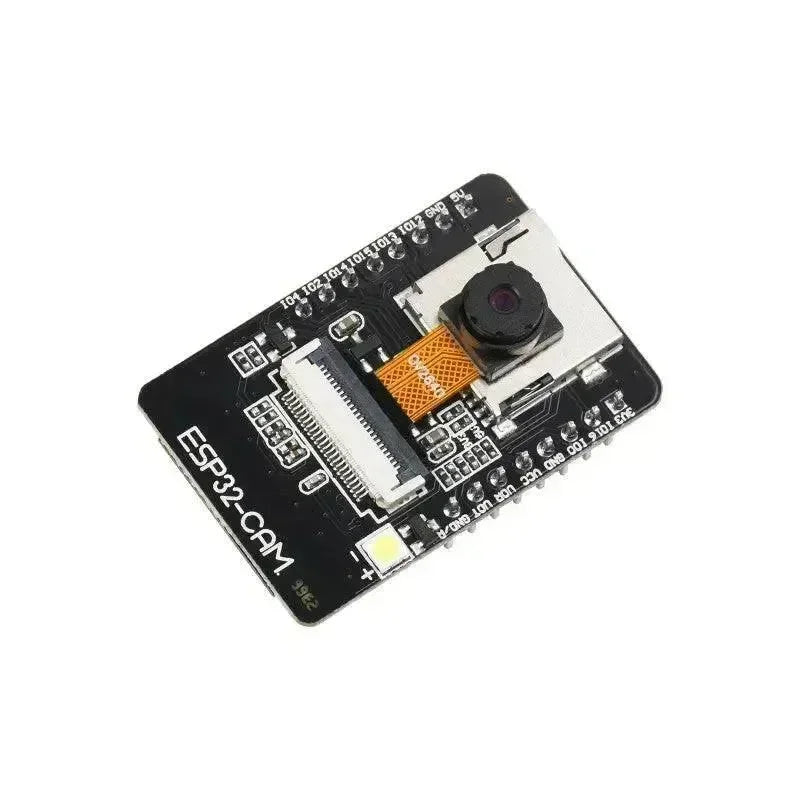
Die ESP32- und ESP32S2-Mikrocontroller sind dank ihrer vielseitigen Funktionen und zuverlässigen Leistung bei IoT-Projekten sehr beliebt. Eine der wesentlichen Funktionen, die Entwickler oft benötigen, ist PWM (Pulsweitenmodulation), und die
AnalogWrite-Bibliothek vereinfacht die Konfiguration von PWM-Kanälen auf diesen Plattformen. Dieser Artikel beleuchtet die wichtigsten Aspekte der ESP32-ESP32S2 AnalogWrite-Bibliothek, einschließlich der PWM-Kanal-Konfigurationen, um Entwicklern zu helfen, ihre Projekte zu optimieren und die Suchmaschinenplatzierung mit diesem praktischen Leitfaden zu verbessern.Was ist die AnalogWrite-Bibliothek?
Die
AnalogWrite-Bibliothek erweitert die Funktionalität der ESP32- und ESP32S2-Boards, indem sie eine präzise Steuerung der PWM-Pins ermöglicht. Während der ESP32 eingebaute PWM-Fähigkeiten besitzt, kann deren direkte Konfiguration komplex sein. Diese Bibliothek vereinfacht die Einrichtung und Nutzung von PWM-Kanälen, sodass Entwickler die Pin-Ausgänge leichter anpassen können, z. B. zum Dimmen von LEDs, Steuern von Motoren oder Erzeugen von Audiosignalen.Wie sehen die Hauptmerkmale aus?
- Einfache PWM-Konfiguration: Die Bibliothek vereinfacht die Konfiguration von PWM-Kanälen und ermöglicht Entwicklern eine einfache Steuerung der Tastverhältnisse.
- Unterstützt mehrere Kanäle: Sowohl ESP32 als auch ESP32S2 Mikrocontroller können mehrere PWM-Kanäle gleichzeitig verwenden, was ihre Fähigkeit verbessert, mehrere Komponenten wie Motoren und LEDs zu steuern.
- Anpassbare Frequenzen: Benutzer können die PWM Frequenz an verschiedene Anwendungen anpassen, wie z. B. Audiosignale oder präzise Motorsteuerung.
- Nahtlose Integration: Die Bibliothek lässt sich leicht in die Arduino IDE integrieren und ermöglicht eine schnelle Entwicklung von IoT-Projekten.
Übersicht der PWM-Kanalkonfiguration
Einstellung PWM Kanäle
Jeder ESP32 PWM-Ausgang benötigt einen separaten Kanal. Der Kanal fungiert als unabhängiger Controller für bestimmte Pins und stellt sicher, dass mehrere Signale gleichzeitig erzeugt werden können.
-
PWM Kanal Bereich: Bis zu 16 Kanäle sind verfügbar, was bedeutet, dass Sie 16 verschiedene Geräte gleichzeitig steuern können.
PWM Frequenzeinstellung
-
Frequenzbereich: Zwischen 1Hz und 40MHz.
-
Wählen Sie eine geeignete Frequenz basierend auf Ihrer spezifischen Anwendung. Zum Beispiel:
-
Niedrige Frequenz (500 Hz): Geeignet für LED Dimmung.
-
Hohe Frequenz (über 20kHz): Wird für Motortreiber verwendet, um hörbare Geräusche zu vermeiden.
-
Arbeitszyklus Anpassung
-
Tastgrad Bereich: 0 % bis 100 %.
-
Ändern Sie den Tastgrad, um zu steuern, wie lange das Signal innerhalb eines Zyklus "ein" bleibt. Dies ist entscheidend für die Steuerung von Helligkeit, Geschwindigkeit oder Spannung.
Grundlegendes Codebeispiel
Das folgende Beispiel zeigt, wie die Bibliothek zur Steuerung eines Servomotors verwendet wird:
// Initialize M5StickC Plus2
#include

Servo myservo;

void setup() {
  myservo.attach(2);  // Attach the servo motor to GPIO2
}

void loop() {
  myservo.write(90);  // Rotate the servo to 90 degrees
  delay(1000);        // Wait for 1 second
  myservo.write(180); // Rotate the servo to 180 degrees
  delay(1000);        // Wait for 1 second
}
✔ Kopiert!
Wichtige Funktionen
Diese Bibliothek bietet verschiedene Funktionen zur Steuerung von Geräten mit simulierten Signalen. Nachfolgend einige wichtige Funktionen:
-
write(): Legt den Tastgrad des Servomotors oder PWM-Ausgangs fest.
-
writeMicroseconds(): Legt die Pulsbreite (in Mikrosekunden) für den Servomotor fest.
-
read(): Ruft den aktuellen Winkel des Servomotors ab.
-
readMicroseconds(): Ruft die aktuelle Pulsbreite (in Mikrosekunden) des Servomotors ab.
-
attach(): Schließt einen Servomotor oder PWM-Ausgang an einen angegebenen GPIO-Pin an.
-
attachPWM(): Schließt einen PWM-Ausgang an einen angegebenen GPIO-Pin an.
-
attached(): Prüft, ob ein Servomotor oder PWM-Ausgang bereits an den angegebenen GPIO-Pin angeschlossen ist.
-
attachInvert(): Verbindet ein invertiertes PWM-Signal mit einem angegebenen GPIO-Pin.
-
attachPin(): Verbindet einen Servomotor oder PWM-Ausgang mit dem angegebenen GPIO-Pin.
-
writePwm(): Legt den Tastgrad des PWM-Ausgangs fest.
-
detach(): Trennt den Servomotor oder PWM-Ausgang vom GPIO-Pin.
-
pause(): Stoppt das PWM-Signal vorübergehend.
-
resume(): Setzt das pausierte Signal fort.
-
setFrequency(): Legt die Frequenz des PWM-Ausgangs fest.
-
setResolution(): Legt die Auflösung des PWM-Ausgangs fest.
-
tone(): Erzeugt einen Ton auf einem Summer mit einer bestimmten Frequenz.
-
noTone(): Stoppt den auf dem Summer erzeugten Ton.
-
printDebug(): Gibt Debugging-Informationen aus.
Optimierung Ihrer Projekte mit AnalogWrite
Die AnalogWrite-Bibliothek vereinfacht nicht nur die PWM-Konfiguration, sondern bietet auch glatte, flimmerfreie Ausgaben, die für verschiedene Anwendungen unerlässlich sind. Mit Unterstützung für mehrere Kanäle können Entwickler komplexe Systeme effizient mit den ESP32- und ESP32S2-Boards steuern.
Fazit: Vereinfachen Sie die PWM-Steuerung mit AnalogWrite
Die ESP32-ESP32S2 AnalogWrite Bibliothek ist ein Wendepunkt für Entwickler, die eine einfache PWM-Steuerung benötigen. Sie ermöglicht schnelles Prototyping und den Einsatz von IoT-Anwendungen wie LED-Anzeigen, Motorsteuerungen und Audio-Generatoren. Durch das Beherrschen der PWM-Kanal-Konfigurationen können Entwickler das volle Potenzial der ESP32-Boards für eine Vielzahl von IoT- und eingebetteten Systemprojekten ausschöpfen.
 openelab.de
 openelab.com


