openelab.de
 openelab.com


Modul vzdáleného hardwaru umožňuje čtení, zápis a monitorování pinů GPIO na vzdáleném uzlu. Konfigurační možnost: Povolen.
Poznámka: Pro verze firmwaru nad 2.5.3 tento modul vyžaduje kompilaci vlastního firmwaru a odstranění build flagu -DMESHTASTIC_EXCLUDE_REMOTEHARDWARE=1 z platformio.ini. I když se konfigurační možnosti tohoto modulu mohou zobrazovat v klientech, nastavení a čtení GPIO je aktuálně podporováno pouze přes Meshtastic Python CLI.
Konfigurační parametry modulu vzdáleného hardwaru
Ujistěte se, že modul je povoleno.
Dostupnost modulu vzdáleného hardwaru v klientech
Android
Všechny konfigurační možnosti modulu vzdáleného hardwaru jsou dostupné v aplikaci pro Android. Otevřete aplikaci Meshtastic a přejděte do Nastavení > Vzdálený hardware.
Jablko
Všechny konfigurační možnosti modulu vzdáleného hardwaru jsou dostupné v aplikacích pro iOS, iPadOS a macOS (verze a vyšší) v Nastavení > Konfigurace modulu > Vzdálený hardware.
CLI
Všechna konfigurační nastavení modulu vzdáleného hardwaru lze spravovat přes Python CLI.
Web
Není implementováno.
Provoz modulu vzdáleného hardwaru
Tip: Přístup k pinům GPIO nese inherentní rizika, protože nesprávná nastavení mohou poškodit nebo zničit váš hardware. Ujistěte se, že plně rozumíte schématu vašeho konkrétního zařízení před pokračováním, protože není poskytována žádná záruka. Používejte tuto funkci na vlastní nebezpečí.
Podporované operace
Můžete nastavit jakýkoli GPIO, číst jakýkoli GPIO a přijímat mesh notifikace kdykoli se stav GPIO změní. Všimněte si, že rychlé přechody—jako například stisky tlačítek—nelze detekovat; pro tyto případy použijte modul Detection Sensor. Výsledky čtení GPIO, stejně jako notifikace o změnách stavu GPIO, jsou také publikovány přes MQTT (pokud je povoleno) ve formátu JSON (pokud je povoleno).
Nastavení
Nejnovější Python nástroje a knihovny můžete nainstalovat spuštěním pip3 install --upgrade meshtastic na Windows, Linuxu nebo OS‑X. Další podrobnosti najdete v sekci Python.
Aby se zabránilo neoprávněnému přístupu, musíte nejprve vytvořit GPIO kanál, který poskytuje autentizovaný přístup k této funkci. Tento kanál musí být přidán jak do lokálního, tak do vzdáleného uzlu a modul musí být povolen na obou zařízeních.
Postup pomocí Python příkazového nástroje je následující:
-
Připojte lokální zařízení přes USB
-
Povolte modul Remote Hardware
| meshtastic --set remote_hardware.enabled true |
-
Vytvořte GPIO kanál:
| meshtastic --ch-add gpio |
-
Ověřte, že kanál byl vytvořen, poté zkopírujte dlouhou „Kompletní URL“, která zahrnuje všechny kanály na zařízení.
| meshtastic --info |
-
Připojte vzdálené zařízení přes USB nebo k němu přistupte přes síť pomocí funkce remote admin.
-
Povolte modul Remote Hardware na vzdáleném zařízení.
| meshtastic --set remote_hardware.enabled true |
-
Konfigurujte vzdálené zařízení, aby se připojilo k GPIO kanálu, který jste dříve vytvořili.
| meshtastic --seturl theurlyoucopiedinstep3 |
Obě zařízení by nyní měla být schopna komunikovat přes GPIO kanál. Pro potvrzení pošlete textovou zprávu z jednoho zařízení na druhé. Můžete také spustit --nodes aby bylo zajištěno, že druhý uzel bude detekován.
Masky
Maska se používá k určení, které GPIO se mají ovládat. Pro GPIO 1 je nastaven bit 1 masky (hexadecimálně 0x2); pro GPIO 2 je nastaven bit 2 masky (0x4); a tak dále. Pro určení správné masky pro pin(y), které chcete použít, může být užitečný Python program (a jeho výstup) uvedený níže.
| >>> for i in range(1,45): ... print(f'GPIO:{i} maska:{hex(2**i)}') ... GPIO:1 maska:0x2 GPIO:2 maska:0x4 GPIO:3 maska:0x8 GPIO:4 maska:0x10 GPIO:5 maska:0x20 GPIO:6 maska:0x40 GPIO:7 maska:0x80 GPIO:8 maska:0x100 GPIO:9 maska:0x200 GPIO:10 maska:0x400 GPIO:11 maska:0x800 GPIO:12 maska:0x1000 GPIO:13 maska:0x2000 GPIO:14 maska:0x4000 GPIO:15 maska:0x8000 GPIO:16 maska:0x10000 GPIO:17 maska:0x20000 GPIO:18 maska:0x40000 GPIO:19 maska:0x80000 GPIO:20 maska:0x100000 GPIO:21 maska:0x200000 GPIO:22 maska:0x400000 GPIO:23 maska:0x800000 GPIO:24 maska:0x1000000 GPIO:25 maska:0x2000000 GPIO:26 maska:0x4000000 GPIO:27 maska:0x8000000 GPIO:28 maska:0x10000000 GPIO:29 maska:0x20000000 GPIO:30 maska:0x40000000 GPIO:31 maska:0x80000000 GPIO:32 maska:0x100000000 GPIO:33 maska:0x200000000 GPIO:34 maska:0x400000000 GPIO:35 maska:0x800000000 GPIO:36 maska:0x1000000000 GPIO:37 maska:0x2000000000 GPIO:38 maska:0x4000000000 GPIO:39 maska:0x8000000000 GPIO:40 maska:0x10000000000 GPIO:41 maska:0x20000000000 GPIO:42 maska:0x40000000000 GPIO:43 maska:0x80000000000 GPIO:44 maska:0x100000000000 |
Správa GPIO přes Python CLI
Poznámka: Můžete ovládat nebo sledovat GPIO vašeho USB připojeného uzlu nastavením --dest na ID lokálního uzlu. V tomto případě není potřeba žádný GPIO kanál.
Zápis GPIO
Příklad: zapnutí GPIO4
|
meshtastic --port /dev/ttyUSB0 --gpio-wrb 4 1 --dest 28979058 |
Čtení GPIO
Příklad: čtení GPIO4
| meshtastic --port /dev/ttyUSB0 --gpio-rd 0x10 --dest 28979058 # Připojeno k rádiu # Čtení GPIO masky 0x10 z !28979058 # Odpověď čtení GPIO gpio_value=16 |
Poznámka: Pokud maska a gpio_value odpovídají, pak je hodnota "zapnuto". Pokud je gpio_value 0, pak je hodnota "vypnuto".
Sledování změn GPIO
Příklad: sledování GPIO4 pro změny
| meshtastic --port /dev/ttyUSB0 --gpio-watch 0x10 --dest 28979058 # Připojeno k rádiu # Sledování GPIO masky 0x10 od !28979058 # Přijato RemoteHardware typ=GPIOS_CHANGED, gpio_value=16 # Přijato RemoteHardware typ=GPIOS_CHANGED, gpio_value=0 # Přijato RemoteHardware typ=GPIOS_CHANGED, gpio_value=16 # < stiskněte ctrl-c pro ukončení > |
Testování GPIO operací
GPIO operace můžete provádět přímo ze svého Python kódu pomocí třídy Meshtastic RemoteHardwareClient. Pro další podrobnosti se podívejte do dokumentace Python API.
Pro potvrzení správné funkce GPIO operací můžete připojit jednoduchou LED a rezistor jako test. Použijte poskytnutý návod jako referenční průvodce.
Požadavky
-
2× zařízení Meshtastic (jedno připojené k místnímu počítači, druhé pouze napájené a použité pro připojení LED)
-
2× vodiče (obvykle černý pro zem a žlutý pro signál, ale lze použít jakékoliv barvy)
-
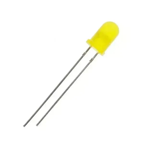
1× LED
-
1× 220 Ω rezistor (volitelné, ale doporučené)
-
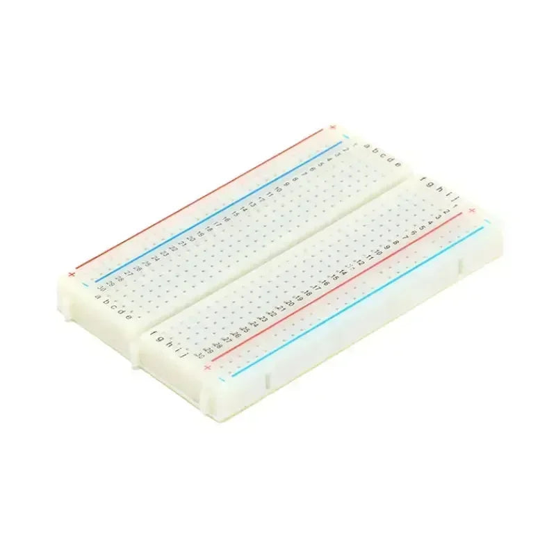
1× breadboard (volitelné)
Příprava
-
Odpojte vzdálené zařízení od jeho zdroje napájení (baterie nebo USB).
-
Připojte rezistor k delší (kladné) nožičce LED a poté připojte žlutý vodič k druhému konci rezistoru.
-
Připojte opačný konec žlutého vodiče k bezpečnému GPIO pinu (například na TLoraV1 můžete použít GPIO21).
-
Připojte černý zemnící vodič z uzemňovacího pinu zařízení (na TLoraV1 je to koncový pin vedle tlačítka RST) k kratší (záporné) nožičce LED.
-
Obnovte napájení zařízení.
Ověření
Ve výchozím nastavení může být pin buď „vypnutý“ nebo „zapnutý“ (nejčastěji „vypnutý“). Pro spuštění příkazů se řiďte níže uvedenými kroky. Například při použití GPIO21 je odpovídající maska 0x200000.