openelab.de
 openelab.com









































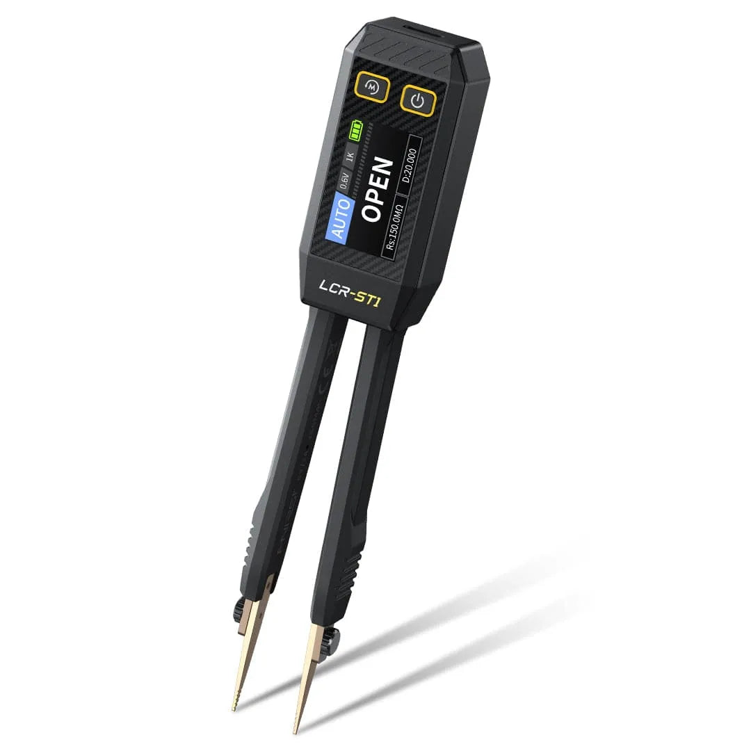
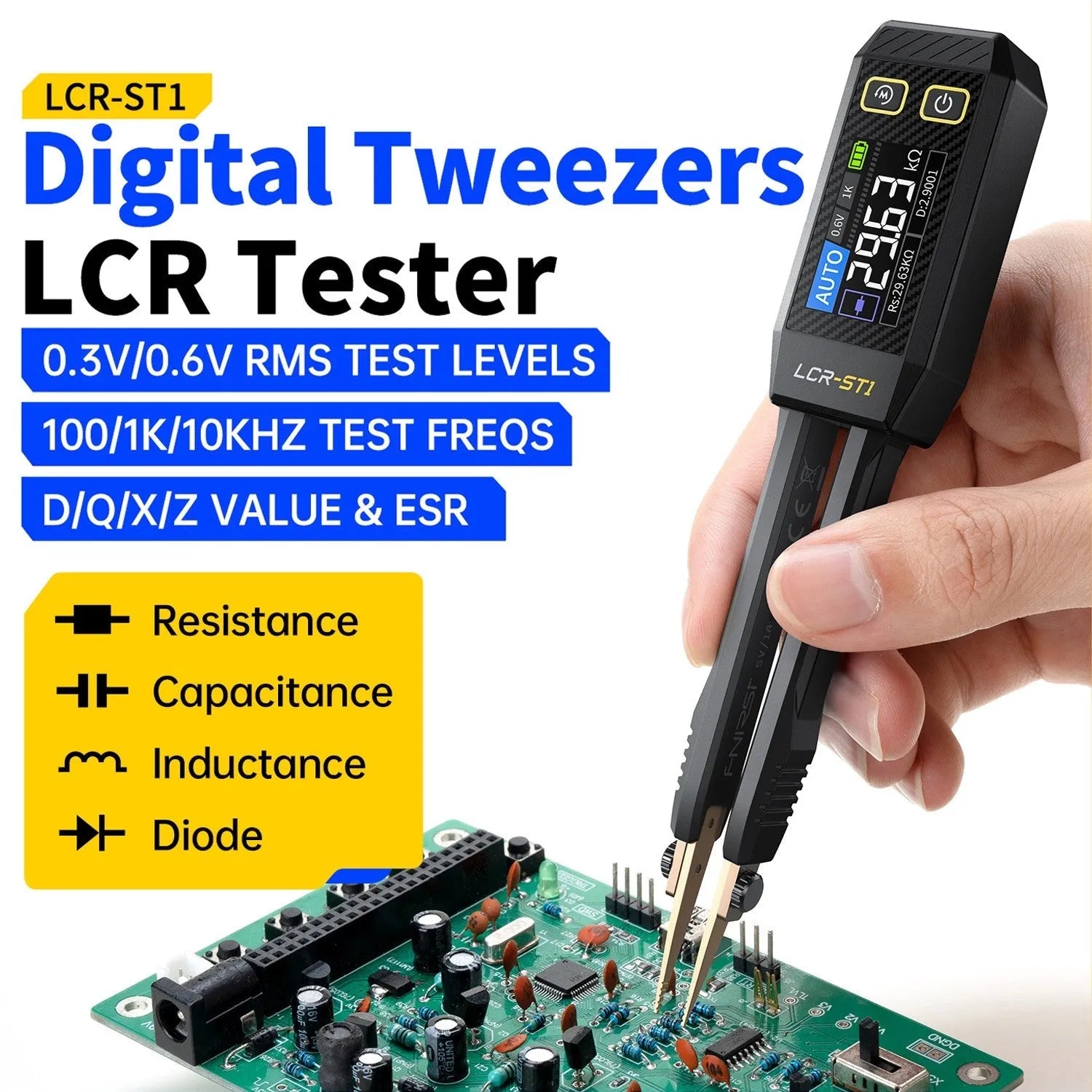
The FNIRSI LCR-ST1 Smart Tweezer LCR ESR SMD Tester is most useful when you need to identify or compare small SMD components without fighting full-size multimeter probes. It can help with SMD resistors, capacitors, inductors, ESR checks, diodes, continuity, and quick component sorting during electronics repair. This tutorial explains how to use it correctly, how to read the results, and when to remove a part from the board before trusting the measurement.
The short answer: use the LCR-ST1 for small passive components and quick repair checks, but do not treat every in-circuit result as final. Discharge capacitors first, clean the pads or terminals, hold the tweezers firmly, choose the right test mode or frequency when needed, and compare suspicious readings against a known-good part or an out-of-circuit measurement.
This OpenELAB tutorial focuses on the FNIRSI LCR-ST1 as a practical SMD and ESR testing tool. It is not meant to replace a full multimeter, oscilloscope, bench power supply, or professional curve tracer. It is a compact smart tweezer tester for fast component identification, comparison, and repair workflow decisions.
Safety boundary: do not use the LCR-ST1 on live high-energy circuits, mains-powered equipment, battery packs, charged capacitors, or unknown high-voltage nodes. Disconnect power, discharge capacitors, and verify the circuit is safe before measuring. If you are working on power supplies, inverters, motor drivers, battery equipment, or mains electronics, follow proper safety procedures and do not rely on a small tweezer tester as your only protection.
Shop FNIRSI LCR-ST1 at OpenELAB
Quick Answer: What Can the FNIRSI LCR-ST1 Test?
| Test type | Useful for | What to watch | Trust level |
|---|---|---|---|
| Resistance | SMD resistors, pull-ups, current sense resistors, unknown resistor sorting | Parallel circuit paths can make in-circuit readings lower than expected. | High for loose parts; conditional for in-circuit parts. |
| Capacitance | SMD capacitors, bulk capacitors, part sorting, comparison between similar boards | Discharge first. In-circuit capacitors are affected by parallel parts and leakage paths. | High for discharged loose parts; conditional in circuit. |
| ESR | Finding suspicious electrolytic, polymer, or decoupling capacitors during repair | ESR depends on frequency, capacitor type, temperature, and circuit context. | Useful for comparison; not a single universal pass/fail number. |
| Inductance | Small inductors, coils, filters, unknown SMD parts | Nearby parallel paths and magnetic parts can affect readings. | Best for loose parts or isolated components. |
| Diode and continuity | Diodes, LEDs, protection parts, fuses, traces, connector pins | In-circuit semiconductors can produce confusing readings through other paths. | Good for quick checks; confirm with a multimeter when needed. |
| DC voltage | Low-energy DC checks where supported by the tester and product guidance | Do not use it as a substitute for a full safety-rated multimeter. Always check the supported voltage range in the product manual before using voltage mode. | Limited support tool, not the main live-circuit instrument. |
Before Testing: Prepare the Board and the Tester
Good LCR measurements start before the tweezer tips touch the component. Small SMD parts are easy to misread because the pads are tiny, oxidized, flux-covered, or connected to other components. A stable reading needs a safe circuit, clean contact, and the right expectation.
- Disconnect power from the board.
- Discharge capacitors before measuring them.
- Check that the component is not connected to a high-voltage or high-energy node.
- Clean obvious oxidation, flux residue, or contamination from the pads.
- Use the pointed tweezer head for dense SMD work and the hook head when it gives better contact.
- Hold the component firmly, but do not push so hard that the part moves or cracks.
- If the reading is unstable, lift one side of the component or remove it for an out-of-circuit check.
OpenELAB lists the LCR-ST1 with automatic and manual test modes, resistance, capacitance, inductance, ESR, diode, continuity, and voltage checks, plus test frequency options including 100Hz, 120Hz, 1kHz, 10kHz, and 100kHz. Use auto mode for quick identification, then use manual mode or a controlled frequency when the result needs more confidence.
Core Measurement Ranges from the OpenELAB Listing
| Function | Listed range or support | Practical use |
|---|---|---|
| Resistance | 0.01 ohm to 10 Mohm | SMD resistors, shorts, low-resistance checks, and component sorting. |
| Capacitance | 1pF to 10mF | Small SMD capacitors, larger capacitors, and comparison checks. |
| Inductance | 1uH to 10H | Small inductors, coils, and unknown SMD inductor sorting. |
| Test frequency | 100Hz, 120Hz, 1kHz, 10kHz, 100kHz | Use consistent frequency when comparing similar components. |
| Other checks | ESR, diode, continuity, DC voltage support | Useful repair clues, but voltage mode should stay within the supported manual range. |
How to Test SMD Resistors
Resistor testing is the easiest place to start because most resistors are non-polar and stable when measured out of circuit. The LCR-ST1 is useful for tiny resistors that are hard to hold with ordinary probes.
Step-by-Step Resistor Test
- Disconnect the board from power.
- Identify the resistor or remove a loose SMD resistor from storage.
- Touch each tweezer tip to one end of the resistor.
- Wait for the reading to settle.
- Compare the displayed value with the marked code, schematic, or known-good board.
- If the value seems too low in circuit, remove one side or measure the part out of circuit.
In circuit, resistor readings often appear lower than expected because other parts form parallel paths. For example, a 10k resistor connected across another path may not read 10k on the board. That does not always mean the resistor is bad. It may mean the circuit around it is being measured too.
How to Test Capacitors and ESR
Capacitor testing is where the LCR-ST1 becomes especially useful for repair. It can measure capacitance and ESR, which helps with component sorting, comparing similar boards, and finding suspicious capacitors. But capacitor testing also has the strongest safety warning: discharge the capacitor first.
Step-by-Step Capacitor Test
- Disconnect power and discharge the capacitor safely.
- For loose capacitors, hold the tweezer tips on both terminals.
- For SMD capacitors on a board, touch both pads without slipping onto nearby components.
- Use auto mode for a quick check.
- If the result looks wrong, try manual capacitance mode or a suitable test frequency.
- Compare the reading with the part marking, schematic, BOM, or a known-good board.
- For precision work, remove or isolate the capacitor before making a final judgement.
How to Think About ESR
ESR means equivalent series resistance. In repair work, a capacitor with high ESR may behave badly even if its capacitance is close to the expected value. This is common in power rails, switching regulators, old electrolytic capacitors, and heat-stressed boards.
Do not use ESR as a single universal pass/fail number. A small ceramic capacitor, a polymer capacitor, and an electrolytic capacitor can have very different normal ESR behavior. ESR also depends on measurement frequency, temperature, part type, and circuit context. The strongest repair use is comparison: compare the suspect part with the same part on a known-good board, or compare several similar capacitors in the same power rail.
| Result | Possible meaning | Next step |
|---|---|---|
| Capacitance close, ESR much higher than similar part | Part may be degraded or heat-stressed. | Confirm out of circuit before replacing when the decision matters. |
| Capacitance much lower than expected | Wrong part, damaged capacitor, or in-circuit measurement problem. | Remove or isolate the part before deciding. |
| Reading unstable | Poor contact, dirty pads, charged capacitor, or parallel circuit effect. | Clean pads, discharge again, and retest with firmer contact. |
| Auto mode identifies the wrong component type | In-circuit paths or unusual component behavior may confuse identification. | Switch to manual mode or test the part out of circuit. |
How to Test Inductors
Inductor testing is useful when sorting loose SMD inductors, comparing filters, or checking whether a coil is open. OpenELAB lists the LCR-ST1 with inductance support, so it can help identify small inductors that do not have readable markings.
Step-by-Step Inductor Test
- Disconnect power from the circuit.
- Discharge nearby capacitors if the inductor is on a board.
- Hold the tweezer tips on both ends of the inductor.
- Use auto mode for quick identification.
- If the value matters, use manual inductance mode and compare with the expected value.
- If the reading is strange in circuit, remove the inductor or compare with a known-good board.
Inductors in power circuits can be connected to low-resistance paths, capacitors, IC pins, and other components. That means an in-circuit reading may show more than the inductor itself. If the goal is exact value identification, measure the part out of circuit.
How to Test Diodes and Continuity
The LCR-ST1 can help with quick diode and continuity checks, especially around small protection parts, LEDs, fuses, traces, and connector pins. This is useful when a board has liquid damage, mechanical damage, or a suspected short near an input connector.
Diode Check Workflow
- Disconnect power from the board.
- Place the tweezer tips across the diode or protection part.
- Read the forward direction result.
- Reverse the tweezer direction and compare.
- If both directions read similar or shorted, check the surrounding circuit before blaming the diode.
In-circuit diode readings can be confusing because current can pass through other semiconductors, IC protection paths, or parallel parts. Use the result as a clue, not as a final verdict. A standard multimeter diode mode can be a useful second check when the reading matters.
Continuity Check Workflow
- Use continuity for traces, fuses, connector pins, switches, and suspected opens.
- Touch both test points with stable pressure.
- Use audible or visual continuity feedback where available.
- If continuity comes and goes, inspect for cracked solder joints, lifted pads, or broken flex cables.
In-Circuit vs Out-of-Circuit Testing
The biggest LCR-ST1 skill is knowing when an in-circuit reading is useful and when it is misleading. In-circuit testing is fast and often good enough for comparison. Out-of-circuit testing is slower but more trustworthy when the value matters.
| Measurement situation | Use in-circuit? | Why |
|---|---|---|
| Comparing two identical board areas | Often useful | Even if readings are affected by surrounding parts, the comparison can reveal a suspicious difference. |
| Identifying a loose SMD part | Not needed | Loose parts usually give cleaner readings because there are no parallel circuit paths. |
| Confirming exact resistor value | Sometimes | Parallel paths can lower the apparent resistance. Lift one side if accuracy matters. |
| Checking capacitor ESR on a power rail | Use carefully | Other capacitors and IC paths can affect readings. Compare similar locations or remove the part. |
| Testing a diode near IC protection pins | Use as a clue only | Other semiconductor paths can make diode behavior appear abnormal. |
Choosing Test Frequency
OpenELAB lists LCR-ST1 test frequency options of 100Hz, 120Hz, 1kHz, 10kHz, and 100kHz. Frequency matters because capacitors and inductors do not behave the same at every frequency. For a quick repair check, auto mode is usually enough. For a more controlled reading, choose a frequency that makes sense for the component type.
- Use lower frequencies for larger capacitors and inductors when appropriate.
- Use higher frequencies for smaller SMD components when appropriate.
- Keep the same frequency when comparing a suspicious part with a known-good part.
- If two frequencies give very different conclusions, remove the component or compare it with documentation.
The goal is consistency. In repair, the most useful measurement is often not the most theoretically perfect number. It is the repeatable number that helps you compare parts under the same conditions.
Common False Readings and How to Fix Them
| Symptom | Likely cause | Fix |
|---|---|---|
| Reading jumps around | Poor contact, dirty pads, weak tweezer pressure, moving part | Clean the contact points, hold the part firmly, and retest. |
| Wrong component type detected | Auto mode confused by in-circuit paths or unusual part behavior | Switch to manual mode or remove the component. |
| Capacitor reads too high or too low | Parallel capacitors, leakage path, charged part, wrong frequency | Discharge, select a suitable mode/frequency, compare, or isolate the part. |
| Resistance reads lower than expected | Parallel resistor or circuit path | Lift one side of the resistor or compare with a schematic. |
| ESR result seems suspicious | Part type, frequency, temperature, or in-circuit effect | Compare against a known-good part under the same conditions. |
Repair Workflow Examples
Example 1: Sorting Unknown SMD Resistors
Place the loose resistor between the tweezer tips, use auto mode, and record the value. If several parts look similar, sort them into labeled groups. For production or precision work, confirm with a dedicated meter or known specification.
Example 2: Comparing Decoupling Capacitors on a Dead Board
Disconnect power and discharge the rail. Measure several similar capacitors on the same rail and compare capacitance and ESR behavior. A single different reading is a clue, not proof. Confirm by isolating or replacing the suspect part if the circuit symptom supports it.
Example 3: Checking an Input Fuse or Trace
Use continuity to check across a fuse, connector pin, or suspected broken trace. If continuity is intermittent, inspect solder joints and mechanical stress points under magnification.
Example 4: Testing an Unknown SMD Inductor
Use auto mode first, then manual inductance mode if needed. If the part is in a power circuit and the reading is unstable, remove it or compare with the same part on a known-good board.
What the LCR-ST1 Does Not Replace
The LCR-ST1 is a strong small-component tool, but it is not the whole repair bench. Use a proper multimeter for general voltage/current/resistance work and safety-rated measurements. Use an oscilloscope when you need waveform shape, ripple, ringing, or signal timing. Use a bench power supply when you need controlled power-up and current limiting. Use a soldering iron or hot air tool when a part needs to be removed, isolated, or replaced.
If your repair workflow includes USB-C chargers, power banks, phones, laptops, embedded boards, and mixed electronics, the LCR-ST1 should be one tool in a larger workflow: inspect first, measure safely, compare results, then repair.
FAQ
Can I use the FNIRSI LCR-ST1 to test components in circuit?
Yes, but treat in-circuit readings as clues. Nearby resistors, capacitors, IC pins, diodes, and board paths can change the reading. For important decisions, remove the part or lift one side before measuring.
Can the LCR-ST1 test capacitor ESR?
Yes. OpenELAB lists ESR support for the LCR-ST1. Use ESR mainly for comparison and troubleshooting context, not as one universal pass/fail number for every capacitor type.
Do I need to discharge capacitors before testing?
Yes. Discharge capacitors before measuring. A charged capacitor can create false readings and may stress the tester input.
Is auto mode enough?
Auto mode is useful for quick identification and sorting. If the result is important, unstable, or surprising, switch to manual mode, choose a suitable test type or frequency, and compare with a known-good part.
Can LCR-ST1 replace a multimeter?
No. It is optimized for small component testing and tweezer-style SMD work. A multimeter is still better for general circuit diagnosis, safety-rated voltage checks, current measurement, and many live-circuit tasks.
What should I do if the reading changes every time?
Clean the pads, improve tweezer contact, stop the part from moving, discharge capacitors again, and try manual mode. If the component is still on a board, in-circuit paths may be affecting the result.
Final Recommendation
Use the FNIRSI LCR-ST1 Smart Tweezer LCR ESR SMD Tester when you regularly work with small SMD resistors, capacitors, inductors, diodes, and unknown parts. It is especially useful for electronics repair, component sorting, board comparison, and quick ESR checks when full-size probes are awkward.
The best workflow is simple: disconnect power, discharge capacitors, clean the contact points, test with stable tweezer pressure, compare suspicious readings, and remove or isolate the part when accuracy matters. Used that way, the LCR-ST1 can save time without encouraging guesswork.